Toyota Tacoma (2015-2018) Service Manual: Removal
REMOVAL
CAUTION / NOTICE / HINT
HINT:
- Use the same procedure for the RH side and LH side.
- The following procedure is for the LH side.
- When removing the front fender wheel opening moulding or quarter panel wheel opening moulding, heat the vehicle body and front fender wheel opening moulding or quarter panel wheel opening moulding using a heat light.
|
Item |
Temperature |
|---|---|
|
Vehicle Body |
40 to 60°C (104 to 140°F) |
|
Front Fender Wheel Opening Moulding or Quarter Panel Wheel Opening Moulding |
20 to 30°C (68 to 86°F) |
NOTICE:
Do not heat the vehicle body or front fender wheel opening moulding or quarter panel wheel opening moulding excessively.
PROCEDURE
1. REMOVE FRONT FENDER MUDGUARD (w/ Mudguard)
(See page .gif) )
)
2. REMOVE FRONT FENDER WHEEL OPENING MOULDING (w/ Mudguard)
|
(a) Using a heat light, heat the front fender wheel opening moulding. |
|
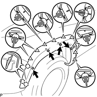
(b) Remove the 4 screws.
(c) Disengage the 3 claws and 9 clips, and peel off the double-sided tape to remove the front fender wheel opening moulding.
3. REMOVE FRONT FENDER WHEEL OPENING MOULDING (w/o Mudguard)
|
(a) Using a heat light, heat the front fender wheel opening moulding. |
|
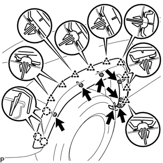
(b) Remove the 7 screws.
(c) Disengage the 3 claws and 9 clips, and peel off the double-sided tape to remove the front fender wheel opening moulding.
4. REMOVE REAR QUARTER PANEL MUDGUARD (w/ Mudguard)
(See page )
5. REMOVE QUARTER PANEL WHEEL OPENING MOULDING (w/ Mudguard)
|
(a) Using a heat light, heat the quarter panel wheel opening moulding. |
|
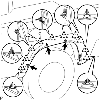
(b) Remove the 3 screws.
(c) Disengage the 10 clips, and peel off the double-sided tape to remove the quarter panel wheel opening moulding.
6. REMOVE QUARTER PANEL WHEEL OPENING MOULDING (w/o Mudguard)
|
(a) Using a heat light, heat the quarter panel wheel opening moulding. |
|
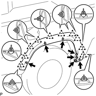
(b) Remove the 7 screws.
(c) Disengage the 10 clips, and peel off the double-sided tape to remove the quarter panel wheel opening moulding.
 Reassembly
REASSEMBLY
CAUTION / NOTICE / HINT
HINT:
Use the same procedure for the RH side and LH side.
The following procedure is for the LH side.
When installing a new front wheel opening ex ...
 Installation
INSTALLATION
CAUTION / NOTICE / HINT
HINT:
Use the same procedure for the RH side and LH side.
The following procedure is for the LH side.
When installing a new front fender wheel o ...
Other materials:
Data Signal Circuit between Radio Receiver and Stereo Jack Adapter
DESCRIPTION
The No. 1 stereo jack adapter assembly sends the sound data signal or image data
signal from a USB device to the radio and display receiver assembly via this circuit.
WIRING DIAGRAM
PROCEDURE
1.
CHECK HARNESS AND CONNECTOR (RADIO AND DISPLAY RECEIVER ASSEMB ...
Blind Spot Monitor Main Switch
Components
COMPONENTS
ILLUSTRATION
Removal
REMOVAL
PROCEDURE
1. REMOVE INSTRUMENT PANEL LOWER CENTER FINISH PANEL
(See page )
2. REMOVE BLIND SPOT MONITOR MAIN SWITCH (WARNING CANCELING SWITCH ASSEMBLY)
(a) Disengage the 2 claws to remove the blind spot monitor main switch ...
Seat Position Sensor
Components
COMPONENTS
ILLUSTRATION
On-vehicle Inspection
ON-VEHICLE INSPECTION
PROCEDURE
1. INSPECT SEAT POSITION AIRBAG SENSOR (for Vehicle not Involved in Collision)
(a) Perform a diagnostic system check (See page
).
2. INSPECT SEAT POSITION AIRBAG SENSOR (for Vehicle Involved in C ...
