Toyota Tacoma (2015-2018) Service Manual: Disassembly
DISASSEMBLY
PROCEDURE
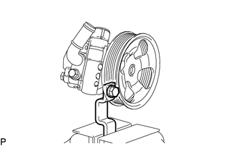
1. FIX VANE PUMP ASSEMBLY
|
(a) Using SST, fix the vane pump assembly in a vise. SST: 09630-00014 09631-00132 NOTICE: When using a vise, do not overtighten it. |
|
2. REMOVE POWER STEERING SUCTION PORT UNION
|
(a) Remove the bolt and suction port union. |
|
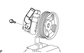
(b) Remove the O-ring from the suction port union.
3. REMOVE FLOW CONTROL VALVE ASSEMBLY
|
(a) Remove the pressure port union. |
|
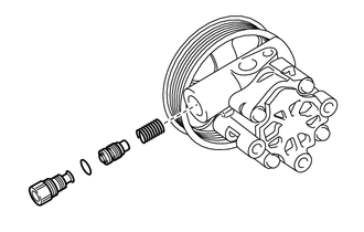
(b) Remove the O-ring from the pressure port union.
(c) Remove the flow control valve assembly and compression spring.
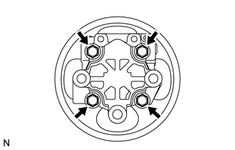
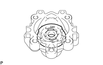
4. REMOVE REAR VANE PUMP HOUSING
|
(a) Remove the 4 bolts and rear vane pump housing from the front vane pump housing. |
|
|
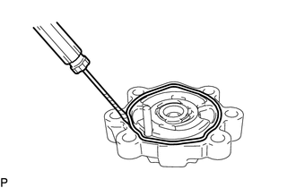
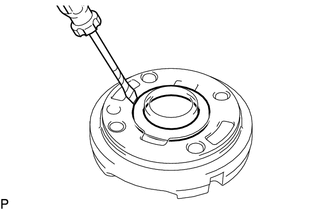
(b) Using a screwdriver, remove the O-ring from the rear vane pump housing. |
|
5. REMOVE PULLEY SHAFT SUB-ASSEMBLY
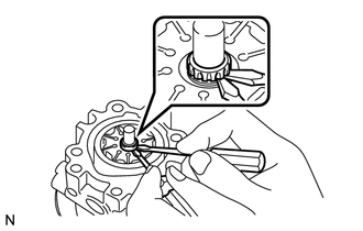
(a) Using a screwdriver, remove the snap ring from the pulley shaft sub-assembly.
|
(b) Remove the pulley shaft. NOTICE: Be careful not to drop or damage the pulley shaft. If damaged, replace it with a new one. |
|
6. REMOVE VANE PUMP ROTOR
|
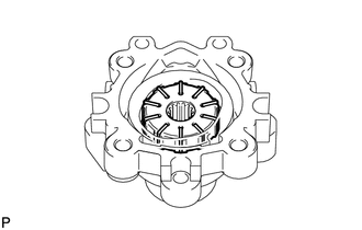
(a) Remove the 10 vane pump plates. NOTICE: Take care not to drop the vane pump plates. |
|
(b) Remove the vane pump rotor from the front vane pump housing.
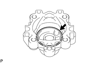
7. REMOVE VANE PUMP CAM RING
|
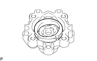
(a) Remove the vane pump cam ring from the front vane pump housing. |
|
8. REMOVE FRONT VANE PUMP SIDE PLATE
|
(a) Remove the front vane pump side plate from the front vane pump housing. |
|
|
(b) Using a screwdriver, remove the O-ring from the front vane pump side plate. |
|
|
(c) Remove the O-ring from the front vane pump housing. |
|
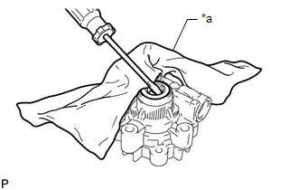
9. REMOVE VANE PUMP HOUSING OIL SEAL
|
(a) Using screwdriver, remove the vane pump housing oil seal. Text in Illustration
NOTICE: Be careful not to damage the front vane pump housing. |
|
 Components
COMPONENTS
ILLUSTRATION
ILLUSTRATION
...
 Removal
REMOVAL
PROCEDURE
1. REMOVE NO. 2 ENGINE UNDER COVER SUB-ASSEMBLY (w/ Off Road Package)
2. REMOVE NO. 1 ENGINE UNDER COVER SUB-ASSEMBLY
3. REMOVE FAN AND GENERATOR V BELT
4. DRAIN POWER STEERI ...
Other materials:
Stop Light Control Relay Malfunction (C1380)
DESCRIPTION
The skid control ECU (brake actuator assembly) inputs the stop light switch signal
and detect the status of the brake operation.
DTC No.
Detection Item
DTC Detection Condition
Trouble Area
C1380
Stop Light Contro ...
Fail-safe Chart
FAIL-SAFE CHART
HINT:
If any of the following auto cancel conditions are detected while the dynamic
radar cruise control system is controlling vehicle speed, the system clears the
stored vehicle speed and cancels control of vehicle speed by the dynamic radar cruise
control system.
Automatic ...
Speed Sensor
Components
COMPONENTS
ILLUSTRATION
Removal
REMOVAL
PROCEDURE
1. REMOVE TRANSMISSION REVOLUTION SENSOR (NT)
(a) Disconnect the transmission revolution sensor (NT) connector.
(b) Remove the bolt and transmission revolution sensor (NT). ...
