Toyota Tacoma (2015-2018) Service Manual: Reassembly
REASSEMBLY
PROCEDURE
1. INSTALL OIL PUMP COVER
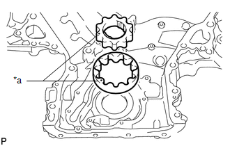
(a) Apply fresh engine oil to the drive and driven rotors.
|
(b) Place the drive and driven rotors into the timing chain cover assembly with the marks facing the oil pump cover side. Text in Illustration
|
|
|
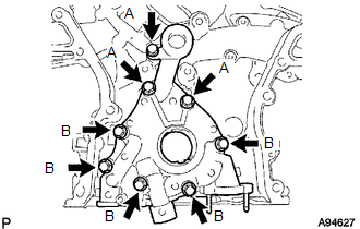
(c) Install the oil pump cover with the 8 bolts. Torque: 9.1 N·m {92 kgf·cm, 81 in·lbf} Bolt Length:
|
|
2. INSTALL OIL PUMP RELIEF VALVE
(a) Coat the oil pump relief valve with engine oil.
(b) Insert the oil pump relief valve and oil pump relief valve spring into the oil pump cover hole.
(c) Using a 27 mm socket wrench, install the oil pump relief valve plug.
Torque:
49 N·m {500 kgf·cm, 36 ft·lbf}
 Installation
INSTALLATION
PROCEDURE
1. INSTALL FRONT CRANKSHAFT OIL SEAL
(a) Using SST and a hammer, tap in a new oil seal until its surface is
flush with the timing chain cover assembly edge.
...
 2gr-fks Starting
...
Other materials:
If your vehicle has to be stopped in an emergency
Only in an emergency, such as if it becomes impossible to stop the vehicle
in the normal way, stop the vehicle using the following procedure:
Steadily step on the brake pedal
with both feet and firmly depress it.
Do not pump the brake pedal repeatedly as this will increase the effort required ...
FCM Destination Information Uninitialized (C1AAA)
DESCRIPTION
When the forward recognition camera is replaced with a new one, the new forward
recognition camera attempts to store the country specification information received
from the main body ECU (multiplex network body ECU). If the forward recognition
camera cannot store the country speci ...
Data List / Active Test
DATA LIST / ACTIVE TEST
1. DATA LIST
NOTICE:
In the table below, the values listed under "Normal Condition" are reference
values. Do not depend solely on these reference values when deciding whether a part
is faulty or not.
HINT:
Using the Techstream to read the Data List allows t ...
