Toyota Tacoma (2015-2018) Service Manual: Reassembly
REASSEMBLY
PROCEDURE
1. INSTALL REAR WHEEL CYLINDER CUP KIT
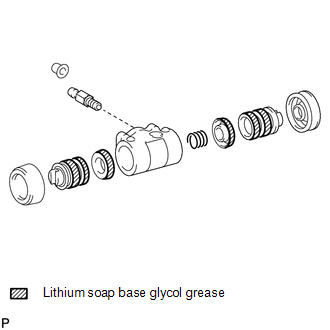
(a) Provisionally tighten the bleeder plug to the rear wheel brake cylinder, and install the bleeder plug cap.
(b) Apply lithium soap base glycol grease to 2 new cylinder cups and the 2 pistons.
(c) Install the cylinder cup onto each piston.
(d) Install the compression spring and 2 pistons onto the rear wheel brake cylinder.
(e) Install the 2 new wheel cylinder boots onto the rear wheel brake cylinder.
2. INSTALL FRONT OR UPPER REAR WHEEL BRAKE CYLINDER ASSEMBLY
.png)
(a) Install the rear wheel brake cylinder assembly with the 2 bolts.
Torque:
9.5 N·m {97 kgf·cm, 84 in·lbf}
(b) Using a union nut wrench, connect the brake tube.
Torque:
without union nut wrench :
15 N·m {155 kgf·cm, 11 ft·lbf}
with union nut wrench :
14 N·m {145 kgf·cm, 10 ft·lbf}
HINT:
- This torque value can be obtained by using a torque wrench with a fulcrum
length of 300 mm (11.8 in.) and a union nut wrench with a fulcrum length
of 22 mm (0.866 in.) (See page
.gif) ).
). - This torque value is effective when the union nut wrench is parallel to the torque wrench.
3. APPLY HIGH TEMPERATURE GREASE
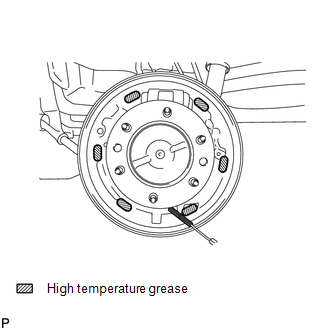
(a) Apply high temperature grease to the shoe attached surface of the backing plate.
4. INSTALL REAR BRAKE SHOE
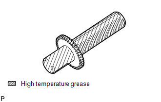
(a) Apply high temperature grease to the adjusting bolt.
|
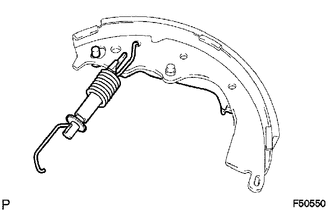
(b) Install the parking brake shoe lever LH and parking brake shoe strut set with the shoe return spring onto the rear brake shoe. |
|
|
(c) Using pliers, install the parking brake shoe strut set, parking brake reaction lever and parking brake shoe lever LH with 2 new C-washers. |
|
.png)
|
(d) Using needle-nose pliers, connect the parking brake cable No. 3 to the parking brake shoe lever LH. |
|
.png)
|
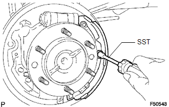
(e) Using SST, install the rear brake shoe, pin, shoe hold down spring and shoe hold down spring cup. SST: 09718-00010 |
|
5. INSTALL FRONT BRAKE SHOE
(a) Install the automatic adjust lever LH, automatic adjust lever spring and parking brake shoe strut lower onto the front brake shoe.
|
(b) Using SST, install the front brake shoe, pin, shoe hold down spring and shoe hold down spring cup. SST: 09718-00010 |
|
|
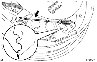
(c) Install the tension spring onto the front brake shoe and rear brake shoe. |
|
|
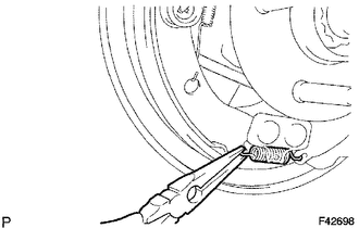
(d) Using needle-nose pliers, install the return spring. |
|
|
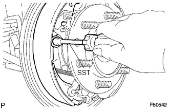
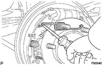
(e) Using SST, install the shoe return spring onto the front brake shoe. SST: 09921-00010 |
|
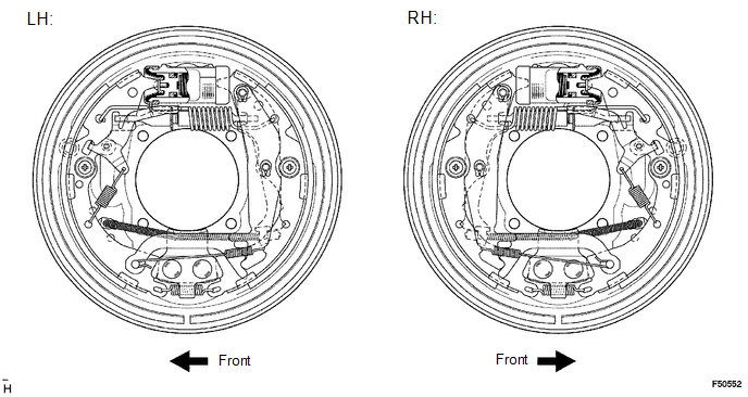
6. INSPECT REAR DRUM BRAKE INSTALLATION
(a) Check that each part is installed properly.
|
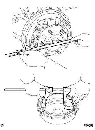
(b) Measure the brake drum inside diameter and the diameter of the brake shoes. Check that difference between the diameters is the specified shoe clearance. Shoe clearance: 0.5 mm (0.0197 in.) NOTICE: There should be no oil or grease adhering to the friction surfaces of the shoe lining and the drum. |
|
 Inspection
INSPECTION
PROCEDURE
1. INSPECT BRAKE DRUM INSIDE DIAMETER
(a) Using a brake drum gauge or equivalent, measure the inside diameter of the
drum.
Standard inside diameter:
254 mm (10.00 in.)
...
 Installation
INSTALLATION
PROCEDURE
1. INSTALL REAR BRAKE DRUM SUB-ASSEMBLY
(a) Install a new drum gasket onto the rear brake drum.
(b) Install the rear brake drum.
2. ADJUST REAR DRUM BRAKE SHOE CLEARANCE
...
Other materials:
Precaution
PRECAUTION
1. IGNITION SWITCH EXPRESSIONS
(a) The type of ignition switch used on this model differs according to the specifications
of the vehicle. The expressions listed in the table below are used in this section.
Expression
Ignition Switch (Position)
Engine ...
Accumulator Low Pressure (C1452)
DESCRIPTION
DTC Code
DTC Detection Condition
Trouble Area
C1452
After braking, the fluid pressure inside the accumulator is below the
threshold within 3.2 seconds.
Hydraulic circuit
Accumulator pressure sen ...
Headlight switch
The headlights can be operated manually.
Turning the end of the lever turns on the lights as follows:
Type A
The daytime running lights turn
on.
The side marker, parking, tail,
license plate, daytime running lights and instrument panel lights turn on.
The headlights and all lights lis ...
