Toyota Tacoma (2015-2018) Service Manual: Components
COMPONENTS
ILLUSTRATION
|
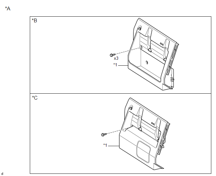
*A |
for Double Cab |
*B |
w/o Woofer |
|
*C |
w/ Woofer |
- |
- |
|
*1 |
LUGGAGE COMPARTMENT SIDE TRAY RH |
- |
- |
ILLUSTRATION
|
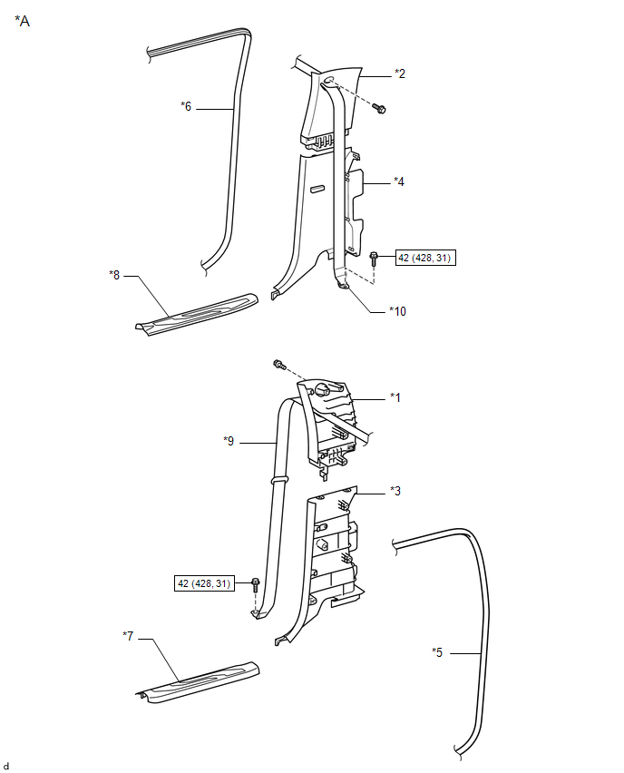
*A |
for Double Cab |
- |
- |
|
*1 |
QUARTER INSIDE TRIM BOARD LH |
*2 |
QUARTER INSIDE TRIM BOARD RH |
|
*3 |
QUARTER TRIM LOWER PANEL LH |
*4 |
QUARTER TRIM LOWER PANEL RH |
|
*5 |
REAR DOOR OPENING TRIM WEATHERSTRIP LH |
*6 |
REAR DOOR OPENING TRIM WEATHERSTRIP RH |
|
*7 |
REAR DOOR SCUFF PLATE LH |
*8 |
REAR DOOR SCUFF PLATE RH |
|
*9 |
REAR SEAT 3 POINT TYPE OUTER BELTASSEMBLY LH |
*10 |
REAR SEAT 3 POINT TYPE OUTER BELTASSEMBLY RH |
.png) |
N*m (kgf*cm, ft.*lbf) : Specified torque |
- |
- |
ILLUSTRATION
|
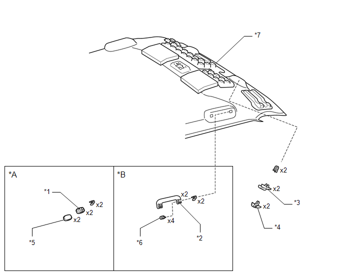
*A |
for Access Cab |
*B |
for Double Cab |
|
*1 |
ASSIST GRIP PLUG |
*2 |
ASSIST GRIP SUB-ASSEMBLY |
|
*3 |
COAT HOOK |
*4 |
COAT HOOK COVER |
|
*5 |
ASSIST GRIP PLUG COVER |
*6 |
ASSIST GRIP COVER |
|
*7 |
ROOF HEADLINING ASSEMBLY |
- |
- |
ILLUSTRATION
|
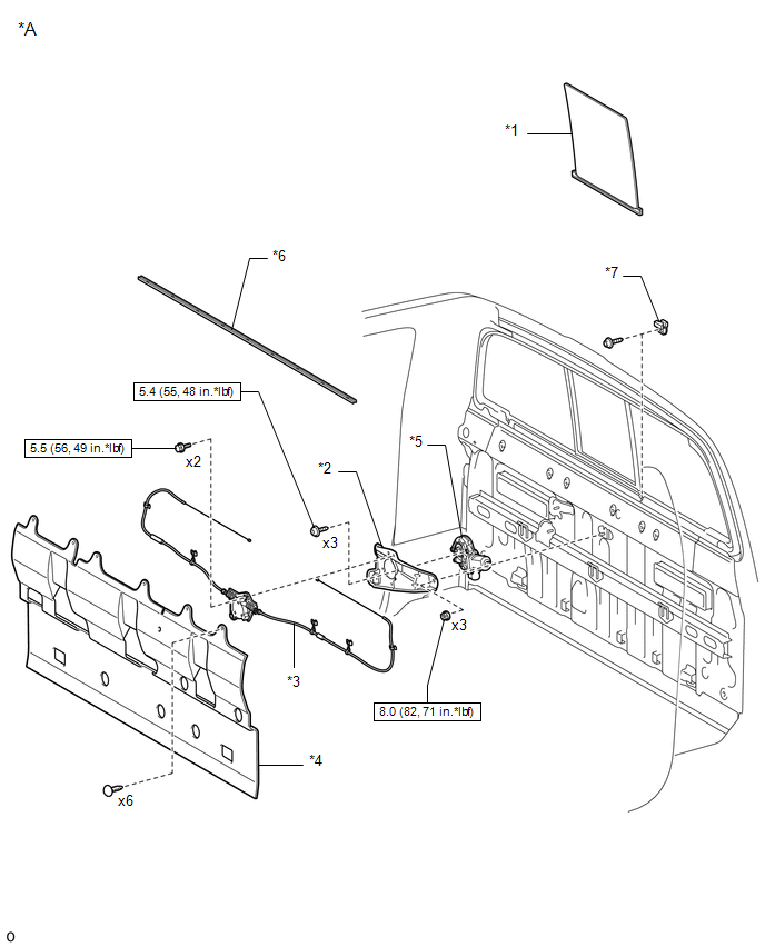
*A |
for Power Slide Type |
- |
- |
|
*1 |
BACK WINDOW SLIDE GLASS SUB-ASSEMBLY |
*2 |
DOOR WINDOW REGULATOR BASE PLATE |
|
*3 |
DOOR WINDOW REGULATOR CABLE SUB-ASSEMBLY |
*4 |
NO. 1 BACK PANEL SILENCER |
|
*5 |
POWER WINDOW REGULATOR MOTOR ASSEMBLY |
*6 |
SEAL |
|
*7 |
STOPPER |
- |
- |
|
|
N*m (kgf*cm, ft.*lbf): Specified torque |
- |
- |
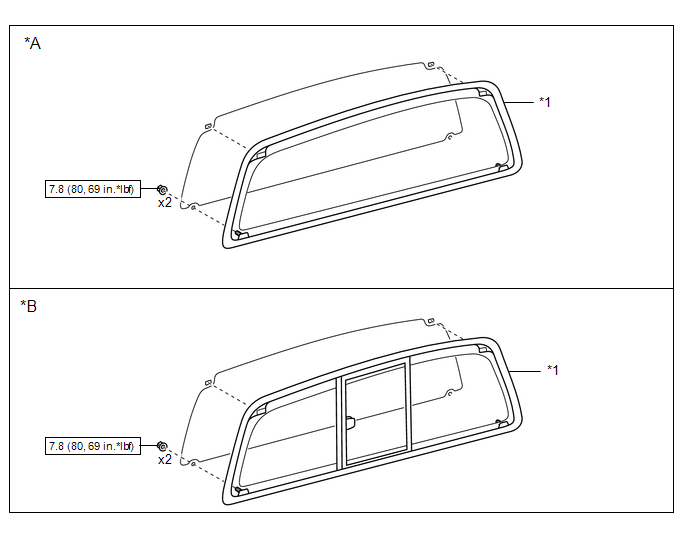
ILLUSTRATION
|
*A |
for Fixed Type |
*B |
for Slide Type |
|
*1 |
BACK WINDOW ASSEMBLY |
- |
- |
|
|
N*m (kgf*cm, ft.*lbf) : Specified torque |
- |
- |

 Inspection
INSPECTION
PROCEDURE
1. INSPECT POWER WINDOW REGULATOR MOTOR ASSEMBLY (for Power Slide Type)
*a
Component without harness connected
(Power Window Regulator Motor Assembly ...
Other materials:
Reassembly
REASSEMBLY
PROCEDURE
1. INSTALL OIL PUMP COVER
(a) Apply fresh engine oil to the drive and driven rotors.
(b) Place the drive and driven rotors into the timing chain cover assembly
with the marks facing the oil pump cover side.
Text in Illustration
*a
...
Diagnosis System
DIAGNOSIS SYSTEM
1. DESCRIPTION
(a) The transponder key ECU assembly controls the engine immobiliser system.
The engine immobiliser system data and Diagnostic Trouble Codes (DTCs) can be read
through the vehicle Data Link Connector 3 (DLC3).
2. CHECK DLC3
(a) Check the DLC3 (See page ).
3. ...
Fail-safe Chart
FAIL-SAFE CHART
HINT:
If any of the following auto cancel conditions are detected while the dynamic
radar cruise control system is controlling vehicle speed, the system clears the
stored vehicle speed and cancels control of vehicle speed by the dynamic radar cruise
control system.
Automatic ...
