Toyota Tacoma (2015-2018) Service Manual: Reassembly
REASSEMBLY
PROCEDURE
1. INSTALL NO. 2 ANTENNA CORD SUB-ASSEMBLY
(a) Using hot-melt glue, install the No. 2 antenna cord sub-assembly as shown in the illustration.
.png)
2. INSTALL NO. 1 ROOF WIRE (w/ Vanity Light)
(a) w/ EC Mirror:
(1) Align the aiming tape as shown in the illustration.
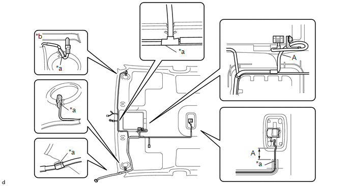
|
*a |
Aiming Tape |
*b |
Adjustment Are |
(2) Using hot-melt glue, install the No. 1 roof wire.
NOTICE:
Do not apply hot-melt glue to the position A shown in the illustration.
HINT:
Use the adjustment area to accommodate any excess length of the No. 1 roof wire.
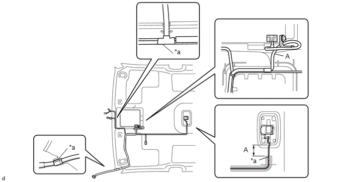
(b) w/o EC Mirror:
(1) Align the aiming tape as shown in the illustration.

|
*a |
Aiming Tape |
*b |
Adjustment Are |
(2) Using hot-melt glue, install the No. 1 roof wire.
NOTICE:
Do not apply hot-melt glue to the position A shown in the illustration.
HINT:
Use the adjustment area to accommodate any excess length of the No. 1 roof wire.
3. INSTALL NO. 1 ROOF WIRE (w/o Vanity Light)
(a) w/ EC Mirror:
(1) Align the aiming tape as shown in the illustration.
|
*a |
Aiming Tape |
- |
- |
(2) Using hot-melt glue, install the No. 1 roof wire.
NOTICE:
Do not apply hot-melt glue to the position A shown in the illustration.
(b) w/o EC Mirror:
(1) Align the aiming tape as shown in the illustration.
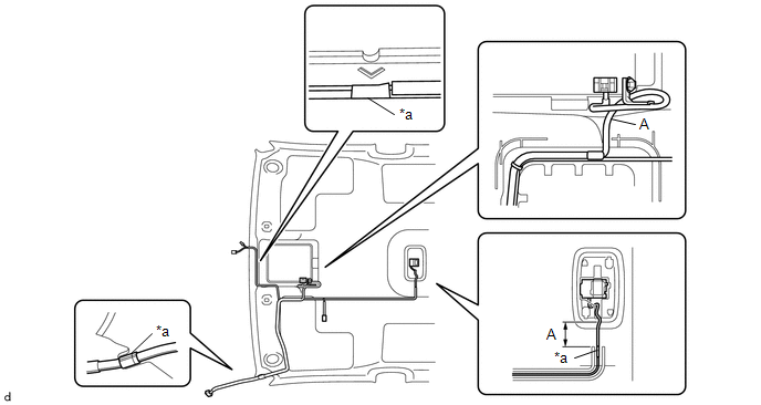
|
*a |
Aiming Tape |
- |
- |
(2) Using hot-melt glue, install the No. 1 roof wire.
NOTICE:
Do not apply hot-melt glue to the position A shown in the illustration.
4. INSTALL MICROPHONE CASE
HINT:
Use the same procedure for Double Cab.
Click here .gif)
5. INSTALL TELEPHONE MICROPHONE ASSEMBLY
Click here
 Installation
INSTALLATION
PROCEDURE
1. INSTALL ROOF HEADLINING ASSEMBLY
(a) Insert the roof headlining assembly into the vehicle from the door.
NOTICE:
Check that the corners of th ...

Other materials:
Differential System(w/o Differential Lock)
Precaution
PRECAUTION
1. Before disassembly, clean the outside of the front and rear differential assembly
and remove any sand and mud to prevent it from entering the assembly during disassembly
and installation.
2. When removing connected parts made of a light alloy, such as front and rear ...
Components
COMPONENTS
ILLUSTRATION
*1
FUEL PUMP ASSEMBLY
*2
FUEL PUMP LIFTER ASSEMBLY
*3
FUEL PUMP LIFTER GUIDE
*4
FUEL PUMP SPACER GASKET
*5
NO. 1 FUEL PIPE SUB-ASSEMBLY
*6
...
Cruise Control Main Switch
Components
COMPONENTS
ILLUSTRATION
Removal
REMOVAL
PROCEDURE
1. REMOVE STEERING PAD ASSEMBLY
(See page )
2. REMOVE CRUISE CONTROL MAIN SWITCH
(a) Disconnect the connector and remove the 2 screws.
(b) Remove the cruise ...
