Toyota Tacoma (2015-2018) Service Manual: Pressure Control Solenoid "D" Performance (Shift Solenoid Valve SLT) (P2714)
SYSTEM DESCRIPTION
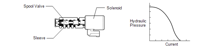
The shift solenoid valve SLT controls the transmission line pressure for smooth transmission operation based on signals from the throttle position sensor and the vehicle speed sensor. The ECM adjusts the current to shift solenoid valve SLT to control hydraulic line pressure coming from the primary regulator valve. Appropriate line pressure assures smooth shifting with varying engine outputs.
|
DTC No. |
DTC Detection Condition |
Trouble Area |
|---|---|---|
|
P2714 |
The ECM detects a malfunction in the shift solenoid valve SLT (ON side) according to the difference in the speed between the turbine and the output shaft, and also by the ATF pressure. (2 trip detection logic) |
|
MONITOR DESCRIPTION
The ECM calculates the amount of clutch slip based on the input turbine speed, output shaft speed, and gear ratio. If the amount of clutch slip exceeds a specified level, the ECM will set this DTC and illuminate the MIL.
When shift solenoid valve SLT remains on, the line pressure goes down and clutch engagement force decreases.
NOTICE:
If the vehicle continues to be driven under these conditions, the clutch will burn up and the vehicle will no longer be drivable.
MONITOR STRATEGY
|
Related DTCs |
P2714: Shift solenoid valve SLT/ON malfunction |
|
Required sensors/Components |
Shift solenoid valve SLT |
|
Frequency of operation |
Continuous |
|
Duration |
ON malfunction: 0.5 sec. |
|
MIL operation |
2 driving cycles |
|
Sequence of operation |
None |
TYPICAL ENABLING CONDITIONS
ON malfunction:|
The monitor will run whenever the following DTCs are not stored |
P0712, P0713 (TFT (ATF temperature) sensor circuit) P0115, P0117, P0118 (ECT (Engine coolant temperature) sensor circuit) P0717, P07BF, P07C0 (Turbine speed sensor circuit) P0722, P077C, P077D (Output speed sensor circuit) P0335 (Crankshaft position sensor circuit (This condition applies only if using fail-safe)) P0748 (Shift solenoid valve SL1 circuit) P0778 (Shift solenoid valve SL2 circuit) P0798 (Shift solenoid valve SL3 circuit) P2810 (Shift solenoid valve SL4 circuit) P2716 (Shift solenoid valve SLT circuit) P0327, P0328, P0332, P0333 (KCS (Knock control sensor) circuit) P0120, P0121, P0122, P0123, P0220, P0222, P0223, P0604, P0606, P060A, P060B, P060D, P060E, P0657, P1607, P2102, P2103, P2111, P2112, P2118, P2119, P2135 (ETCS (Electronic throttle control system)) U0100 (CAN communication system) |
|
TFT (ATF temperature) sensor circuit |
Not circuit malfunction |
|
ECT (Engine coolant temperature) sensor circuit |
Not circuit malfunction |
|
Turbine speed sensor circuit |
Not circuit malfunction |
|
Output speed sensor circuit |
Not circuit malfunction |
|
Shift solenoid valve SL1 circuit |
Not circuit malfunction |
|
Shift solenoid valve SL2 circuit |
Not circuit malfunction |
|
Shift solenoid valve SL3 circuit |
Not circuit malfunction |
|
Shift solenoid valve SL4 circuit |
Not circuit malfunction |
|
Shift solenoid valve SLT circuit |
Not circuit malfunction |
|
KCS (Knock control sensor) circuit |
Not circuit malfunction |
|
ETCS (Electronic throttle control system) |
Not system down |
|
CAN communication system |
Not system down |
|
Transmission range |
"D" |
|
Duration time from shifting "N" to "D" |
4 sec. or more |
|
TFT (ATF temperature) |
-10┬░C (14┬░F) or higher |
|
Engine |
Running |
TYPICAL MALFUNCTION THRESHOLDS
One of the following conditions is met: ON malfunction (A), (B), (C), (D), (E), (F) or (G)
ON malfunction (A):|
Summation of clutch heat generations |
Specified value |
|
Shift solenoid valve SL1 ON malfunction |
Detected |
|
Shift solenoid valve SL1 OFF malfunction |
Detected |
|
Shift solenoid valve SL2 OFF malfunction |
Detected |
|
Shift solenoid valve SL3 OFF malfunction |
Detected |
|
Shift solenoid valve SL4 ON malfunction |
Detected |
|
Shift solenoid valve SL4 OFF malfunction |
Detected |
CAUTION / NOTICE / HINT
NOTICE:
- Perform the universal trip to clear permanent DTCs (See page
.gif) ).
). - Perform registration and/or initialization when parts related to the
automatic transmission are replaced (See page
).
HINT:
After the repair, clear the DTCs and perform the following procedure to check that DTCs are not output.
- Perform the D Position Shift Test in Road Test (See page
).*1
- Turn the ignition switch off.
- Perform step (*1) again.
- Check for DTCs again (See page ).
PROCEDURE
|
1. |
CHECK OTHER DTCS OUTPUT (IN ADDITION TO DTC P2714) |
(a) Connect the Techstream to the DLC3.
(b) Turn the ignition switch to ON.
(c) Turn the Techstream on.
(d) Enter the following menus: Powertrain / Engine and ECT / Trouble Codes.
(e) Read the DTCs using the Techstream.
Result|
Result |
Proceed to |
|---|---|
|
Only DTC P2714 is output |
A |
|
P2714 and other DTCs are output |
B |
HINT:
If a solenoid is stuck on, DTCs for several solenoids including the malfunctioning solenoid will be detected.
| A | .gif) |
GO TO STEP 4 |
|
.gif)
|
2. |
PERFORM ACTIVE TEST USING TECHSTREAM (ACTIVATE THE SOLENOID (SLT)) |
NOTICE:
- Perform the test while the ATF (Automatic Transmission Fluid) temperature is between 50 and 80┬░C (122 and 176┬░F).
- Be careful to prevent the hose of SST from interfering with the exhaust pipe.
- This check must be conducted after checking and adjusting the engine.
- Perform the test with the air conditioning off.
HINT:
Using the Techstream to perform Active Tests allows relays, VSVs, actuators and other items to be operated without removing any parts. This non-intrusive functional inspection can be very useful because intermittent operation may be discovered before parts or wiring is disturbed. Performing Active Tests early in troubleshooting is one way to save diagnostic time. Data List information can be displayed while performing Active Tests.
(a) Turn the ignition switch off.
(b) Lift the vehicle up.
|
(c) Remove the test plug from the transmission case and connect SST. |
|
.png)
SST: 09993-19015
09993-00010
09993-00040
(d) Lower the vehicle.
(e) Fully apply the parking brake and chock the 4 wheels.
(f) Connect the Techstream to the DLC3.
(g) Start the engine.
(h) Warm up the ATF (Automatic Transmission Fluid).
(i) Measure the line pressure when the engine is idling.
(j) Turn the Techstream on.
(k) Enter the following menus: Powertrain / Engine and ECT / Active Test.
(l) Follow the instructions on the Techstream and perform the Active Test.
(m) Measure the line pressure with SST.
Engine and ECT|
Tester Display |
Test Part |
Control Range |
Diagnostic Note |
|---|---|---|---|
|
Activate the Solenoid (SLT)* |
Operates shift solenoid valve SLT to raise the line pressure. |
ON/OFF HINT: ON: No action (normal operation) OFF: Line pressure up (When the Active Test of "Activate the Solenoid (SLT)" is performed, the ECM commands the shift solenoid valve SLT to turn off). |
[Vehicle Condition]
|
*: The "Activate the solenoid (SLT)" Active Test is performed to allow confirmation
that the line pressure changes. The line pressure changes are confirmed using the
same SST that is used for the Hydraulic Test (See page
).
HINT:
Note that the pressure readings for the Active Test and Hydraulic Test are different.
OK:
The line pressure changes as specified when performing the Active Test.
| NG | |
GO TO STEP 4 |
|
|
3. |
PERFORM ACTIVE TEST USING TECHSTREAM (CONTROL THE SHIFT POSITION) |
NOTICE:
This test should always be performed with at least 2 people.
(a) Warm up the engine.
(b) Turn the ignition switch off.
(c) Connect the Techstream to the DLC3.
(d) Turn the ignition switch to ON.
(e) Turn the Techstream on.
(f) Enter the following menus: Powertrain / Engine and ECT / Active Test.
(g) According to the display on the Techstream, perform the Active Test.
HINT:
Comparing the gear commanded by the Active Test with the actual gear enables
confirmation of the problem (See page ).
|
Tester Display |
Test Part |
Control Range |
Diagnostic Note |
|---|---|---|---|
|
Control the Shift Position |
Operates the shift solenoid valves to allow gears to be selected manually. |
|
Can be used to check the operation of the shift solenoid valves. Up-shifts and down-shifts should be performed consecutively. A 10 second interval is required between gear changes. Do not down-shift at high speeds. Doing so will damage the automatic transmission. [Vehicle Condition]
|
HINT:
- This test can be conducted when the vehicle speed is 50 km/h (31 mph) or less.
- The 4th to 5th and 5th to 6th up-shift must be performed with the accelerator pedal released.
- The 6th to 5th and 5th to 4th down-shift must be performed with the accelerator pedal released.
- Do not operate the accelerator pedal for at least 2 seconds after shifting and do not shift successively.
- The gear commanded by the ECM is shown in the Data List / Shift Status display on the Techstream.
(h) Compare the ECM commanded gear and the actual gear.
Result|
Actual Gear during Malfunction |
ECM Commanded Gear |
Proceed to |
||||||
|---|---|---|---|---|---|---|---|---|
|
1st |
2nd |
3rd |
4th |
5th |
6th |
|||
|
Shift solenoid valve SL1 |
Stuck ON |
1st |
2nd |
3rd |
4th |
4th |
4th |
A |
|
Stuck OFF |
N*1 |
N*1 |
N*1 |
N*1 |
5th |
6th |
||
|
Shift solenoid valve SL2 |
Stuck ON |
4th |
4th |
4th |
4th |
5th |
6th |
B |
|
Stuck OFF |
1st |
2nd |
3rd |
1st |
N*1 |
N*1 |
||
|
Shift solenoid valve SL3 |
Stuck ON |
2nd |
2nd |
3rd |
4th |
5th |
6th |
C |
|
Stuck OFF |
1st |
1st |
3rd |
4th |
5th |
N*1 |
||
|
Shift solenoid valve SL4 |
Stuck ON |
3rd |
3rd |
3rd |
4th |
5th |
5th |
D |
|
Stuck OFF |
1st |
2nd |
1st |
4th |
N*1 |
6th |
||
|
Shift solenoid valve SLT |
Stuck ON |
N*2 |
N*2 |
N*2 |
N*2 |
N*2 |
N*2 |
E |
|
Stuck OFF*3 |
1st |
2nd |
3rd |
4th |
5th |
6th |
||
HINT:
- *1: Neutral
- *2: If shift solenoid valve SLT is stuck on, the line pressure will be low. Therefore, the amount of torque that can be transmitted by each gear is lower than the normal limit. When the engine power exceeds this lowered limit, the engine speed will increase freely.
- *3: When shift solenoid valve SLT is stuck off, gear shifting is normal.
| A | |
GO TO DTC CHART (RELATED SHIFT SOLENOID VALVE SL1 PERFORMANCE DTC P0746) |
| B | |
GO TO DTC CHART (RELATED SHIFT SOLENOID VALVE SL2 PERFORMANCE DTC P0776) |
| C | |
GO TO DTC CHART (RELATED SHIFT SOLENOID VALVE SL3 PERFORMANCE DTC P0796) |
| D | |
GO TO DTC CHART (RELATED SHIFT SOLENOID VALVE SL4 PERFORMANCE DTC P2808) |
|
|
4. |
INSPECT SHIFT SOLENOID VALVE SLT |
|
(a) Remove shift solenoid valve SLT (See page
|
|
.png)
(b) Measure the resistance according to the value(s) in the table below.
Standard Resistance:
|
Tester Connection |
Condition |
Specified Condition |
|---|---|---|
|
1 - 2 |
20┬░C (68┬░F) |
5.0 to 5.6 ╬® |
(c) Apply 12 V battery voltage to the shift solenoid valve and check that the valve moves and makes an operating noise.
OK:
|
Measurement Condition |
Specified Condition |
|---|---|
|
Valve moves and makes an operating noise |
|
*1 |
Shift Solenoid Valve SLT |
| NG | |
REPLACE SHIFT SOLENOID VALVE SLT |
|
|
5. |
INSPECT TRANSMISSION VALVE BODY ASSEMBLY |
(a) Check the transmission valve body assembly (See page
).
OK:
There is no foreign matter on each valve and they operate smoothly.
| OK | |
REPAIR OR REPLACE AUTOMATIC TRANSMISSION ASSEMBLY |
| NG | |
REPAIR OR REPLACE TRANSMISSION VALVE BODY ASSEMBLY |
 Transmission Range Sensor Circuit Malfunction (PRNDL Input) (P0705)
DESCRIPTION
The park/neutral position switch detects the shift lever position and sends signals
to the ECM.
DTC No.
DTC Detection Condition
Trouble Area
...
 Transmission Fluid Temperature Sensor "A" Circuit Low Input (P0712,P0713)
DESCRIPTION
The No. 1 ATF temperature sensor converts the fluid temperature into a resistance
value for use by the ECM.
The ECM applies a voltage to the temperature sensor through terminal THO1 of ...
Other materials:
Short in Curtain Shield Squib LH Circuit (B1835/58-B1838/58)
DESCRIPTION
The driver side curtain shield squib circuit consists of the airbag sensor assembly
and the curtain shield airbag assembly LH.
The circuit signals the SRS to deploy when airbag deployment conditions are met.
These DTCs are set when a malfunction is detected in the driver side curtai ...
Removal
REMOVAL
PROCEDURE
1. REMOVE AIR CONDITIONING CONTROL ASSEMBLY (for Automatic Air Conditioning System)
Click here
2. REMOVE AIR CONDITIONING CONTROL ASSEMBLY (for Manual Air Conditioning System)
Click here
3. REMOVE LOWER NO. 2 INSTRUMENT PANEL AIRBAG ASSEMBLY
Click here
4. REMOVE INSTR ...
Destination Information Undefined (C1AB8)
DESCRIPTION
This DTC is stored when correct destination information is not sent from the
main body ECU (multiplex network body ECU) and destination information cannot be
confirmed after a blind spot monitor has been replaced.
DTC Code
DTC Detection Condition
Tr ...
