Toyota Tacoma (2015-2018) Service Manual: Parts Location
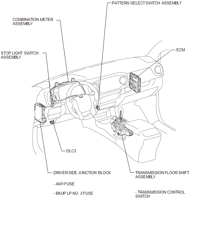
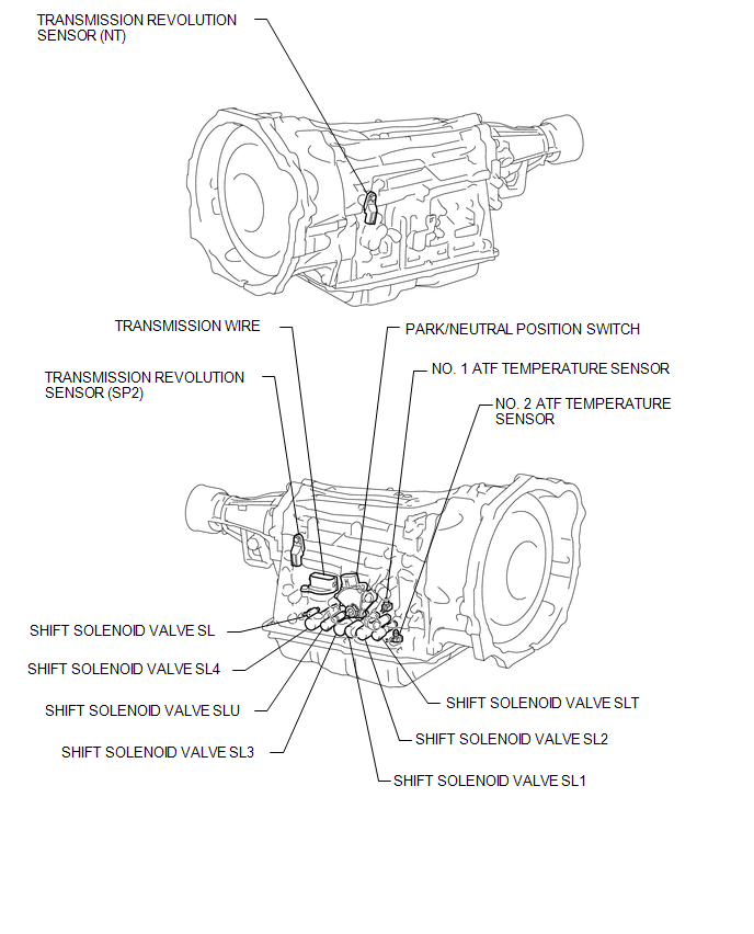
PARTS LOCATION
ILLUSTRATION
.png)
ILLUSTRATION
ILLUSTRATION
 Definition Of Terms
DEFINITION OF TERMS
Term
Definition
Monitor description
Description of what the ECM monitors and how it detects malfunctions
(monitoring purpose ...
 How To Proceed With Troubleshooting
CAUTION / NOTICE / HINT
HINT:
The ECM of this system is connected to the CAN communication system.
Therefore, before starting troubleshooting, make sure to check that there
is no tro ...
Other materials:
Customize Parameters
CUSTOMIZE PARAMETERS
PROCEDURE
1. CUSTOMIZE INTUITIVE PARKING ASSIST SYSTEM
(a) Customizing with the Techstream
NOTICE:
When the customer requests a change in a function, first make sure that
the function can be customized.
Be sure to make a note of the current settings before c ...
Auxiliary boxes
Front
Pull the lid down.
Under the rear seats (Access Cab
models)
Pull up the lever.
Raise the bottom cushion up.
Turn the knob counterclockwise.
Open the lid.
Press the lid against the bottom
of the lower cushion until it is supported by the hookand- loop fastener.
Make sur ...
Vehicle Speed Signal Circuit between Radio Receiver and Combination Meter
DESCRIPTION
for Navigation Function:
The navigation receiver assembly receives a vehicle speed signal from
the combination meter assembly and sends the signal to navigation receiver
assembly.
for Automatic Sound Levelizer (ASL):
This circuit is necessary for the Aut ...
