Toyota Tacoma (2015-2018) Service Manual: Parts Location
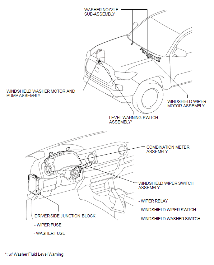
PARTS LOCATION
ILLUSTRATION

 Precaution
PRECAUTION
1. IGNITION SWITCH EXPRESSIONS
(a) The type of ignition switch used on this model differs depending on the specifications
of the vehicle. The expressions listed in the table below are u ...
Other materials:
Dtc Check / Clear
DTC CHECK / CLEAR
1. CHECK DTC
(a) Connect the Techstream to the DLC3.
(b) Turn the ignition switch to ON.
(c) Turn the Techstream on.
(d) Enter the following menus: Body Electrical / (desired system) / Trouble Codes.
(e) Check the details of the DTC(s) (See page
).
2. CLEAR DTC
(a) Connec ...
Engine (ignition) switch
■ Engine switch
LOCK
The steering wheel is locked and the key can be removed.
(Vehicles with an automatic transmission: The key can be removed only when the
shift lever is in P.)
ACC
Some electrical components such as the audio system can be used.
ON
All electrical components can ...
Pressure Control Solenoid "A" Actuator Stuck Off (P07457F)
SYSTEM DESCRIPTION
The ECM uses the vehicle speed signal and signals from the transmission revolution
sensors (NT, SP2) to detect the actual gear (1st, 2nd, 3rd, 4th, 5th or 6th gear).
The ECM compares the actual gear with the shift schedule in the ECM memory to
detect mechanical problems of t ...
