Toyota Tacoma (2015-2018) Service Manual: Parts Location
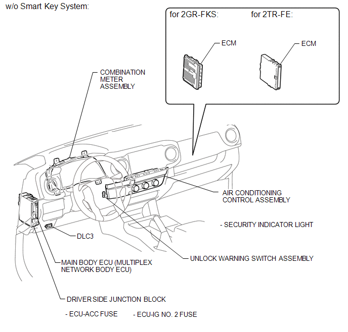
PARTS LOCATION
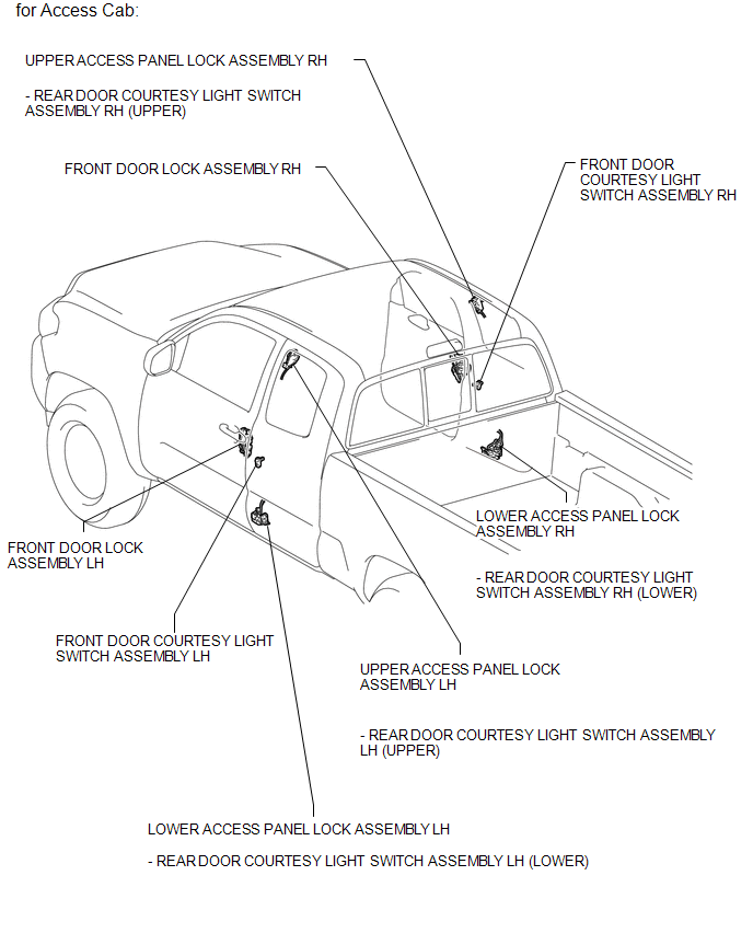
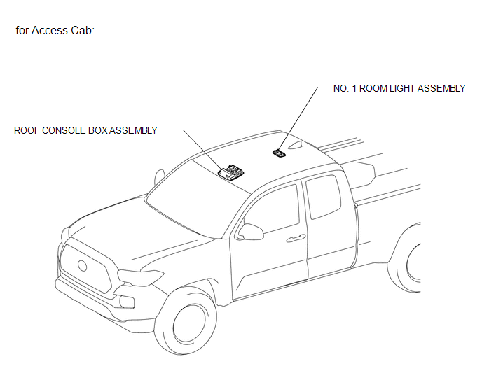
ILLUSTRATION
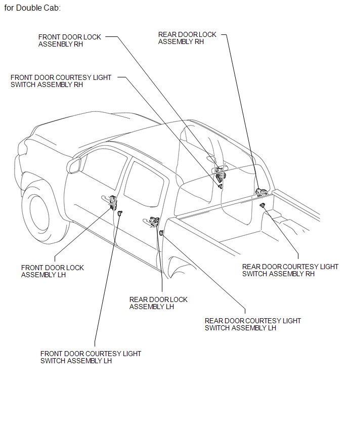
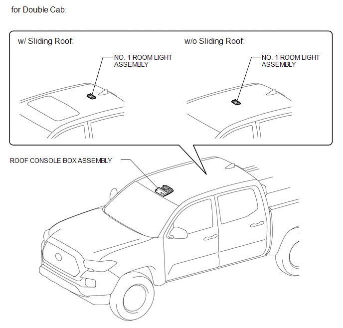
ILLUSTRATION
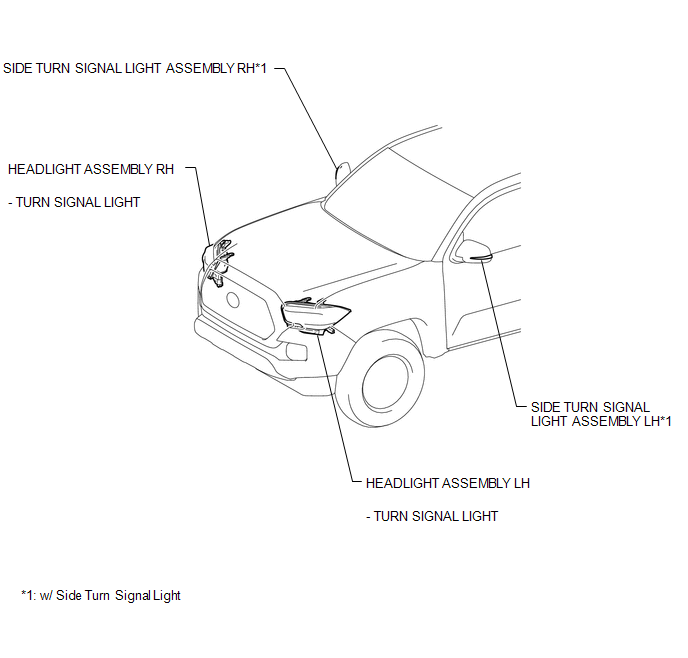
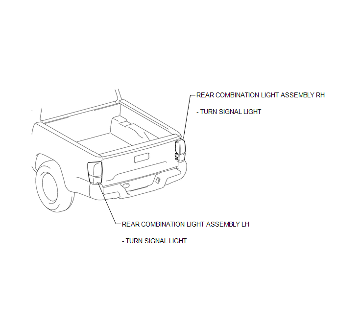
ILLUSTRATION
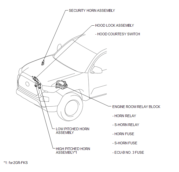
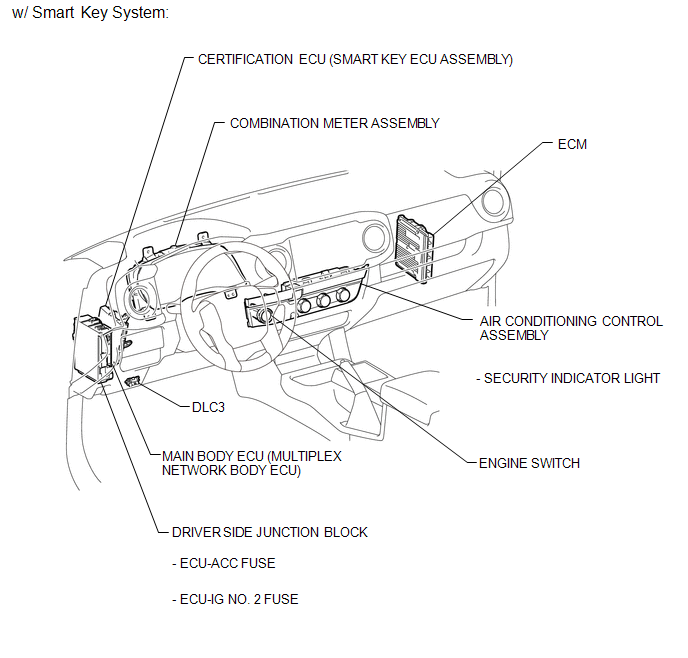
ILLUSTRATION
ILLUSTRATION
ILLUSTRATION
ILLUSTRATION
ILLUSTRATION
ILLUSTRATION

 Precaution
PRECAUTION
1. IGNITION SWITCH EXPRESSIONS
(a) The type of ignition switch used on this model differs according to the specifications
of the vehicle. The expressions listed in the table below are u ...
Other materials:
Problem Symptoms Table
PROBLEM SYMPTOMS TABLE
NOTICE:
When replacing the skid control ECU (brake actuator assembly), sensor, etc.,
turn the ignition switch off.
HINT:
Use the table below to help determine the cause of problem symptoms.
If multiple suspected areas are listed, the potential causes of the s ...
Voice Guidance does not Function
PROCEDURE
1.
CHECK VOICE GUIDANCE SETTING
(a) Check that the voice guidance setting is not off.
OK:
Voice guidance setting is not off.
NG
CHANGE THE VOICE GUIDANCE SETTING TO ON
OK
...
If your vehicle overheats
The following may indicate that your vehicle is overheating.
● The needle of the engine coolant temperature gauge (→P. 155) enters the red
zone or a loss of engine power is experienced.
(For example, the vehicle speed does not increase.) ● Steam comes out from under
the hood. ...
