Toyota Tacoma (2015-2018) Service Manual: System Description
SYSTEM DESCRIPTION
1. BRIEF DESCRIPTION
(a) The Controller Area Network (CAN) is a serial data communication system for real time application. It is a vehicle multiplex communication system which has a high communication speed and the ability to detect malfunctions.
(b) Using the CANH and CANL bus lines as a pair, CAN communication is performed using a voltage differential. (A base voltage is applied to the pair of lines and a voltage differential is created when communicating.)
(c) Many ECUs or sensors installed to the vehicle operate by sharing information and communicating with each other.
(d) The V bus has a termination circuit with a resistor of 60 Ω, and the bus 2, bus 3, bus 5 and sub bus 1 each have termination circuits with two resistors of 120 Ω.
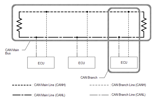
2. DEFINITION OF TERMS
(a) Main bus
(1) The main bus is a wire harness between the two terminating resistors on the bus. This is the main bus in the CAN communication system.
(b) Branch
(1) A branch is a wire harness which diverges from the main bus to an ECU or sensor.
(c) Terminating resistors
(1) Two resistors of 120 Ω are installed in parallel across the ends of the CAN main bus lines. They are called terminating resistors. These resistors allow the changes of the voltage differential between the CAN bus lines to be accurately judged. To allow proper function of CAN communication, it is necessary to have both terminating resistors installed. Since the two resistors are installed in parallel, this results in a measurement of approximately 60 Ω.
3. CIRCUIT DESCRIPTION
(a) The V bus has a termination circuit with a resistor of 60 Ω.
(b) The bus 2, bus 3 and bus 5 each have termination circuits with two resistors of 120 Ω.
4. TROUBLESHOOTING REMARKS
(a) DTCs for the CAN communication system can be checked using the Techstream. The DLC3 is connected to the CAN communication system, but no DTCs exist regarding problems in the DLC3 or the DLC3 branch lines. If there is a malfunction in the DLC3 or the DLC3 branch lines, ECUs on the CAN cannot output DTCs to the Techstream.
5. DIAGNOSTIC TROUBLE CODES FOR CAN COMMUNICATION SYSTEM
HINT:
See Diagnosis System.
Click here .gif)
6. HOW TO DISTINGUISH CONNECTOR OF CAN JUNCTION CONNECTOR
(a) In the CAN communication system, the shape of connectors connected to the CAN junction connector which has a ground terminal are the same. The connectors connected to the CAN junction connector can be distinguished by the colors of the bus lines and the connecting side of the junction connector.
HINT:
See Terminals of ECU for bus line color or the shape of connectors.
Click here
 Problem Symptoms Table
PROBLEM SYMPTOMS TABLE
HINT:
Use the table below to help determine the cause of problem symptoms.
If multiple suspected areas are listed, the potential causes of the symptoms
are lis ...
 Utility
UTILITY
INITIALIZE THE CONNECTION INFORMATION OF A GATEWAY FUNCTION EQUIPPED ECU (BUS
MONITOR ECU)
(a) Connect the Techstream to the DLC3.
(b) Turn the ignition switch to ON.
(c) Turn the Techst ...
Other materials:
Turn Signal Switch Circuit
DESCRIPTION
The combination meter assembly receives the turn signal switch information and
controls the turn signal lights.
WIRING DIAGRAM
PROCEDURE
1.
READ VALUE USING TECHSTREAM (TURN SIGNAL SWITCH)
(a) Connect the Techstream to the DLC3.
(b) Turn the igni ...
Correct driving posture
Drive in a good posture as follows:
Sit upright and well back in the
seat.
Adjust the position of the seat
forward or backward to ensure the pedals can be reached and easily depressed to
the extent required.
Adjust the seatback so that the
controls are easily operable.
Adjust the t ...
Cellular Phone Inspection
PROCEDURE
1.
CHECK USAGE CONDITION
(a) Check that the vehicle and cellular phone meet the following conditions:
NOTICE:
If changing cellular phone settings, updating software, etc. is necessary, make
sure to obtain the permission of the customer before performin ...
