Toyota Tacoma (2015-2018) Service Manual: Parts Location
PARTS LOCATION
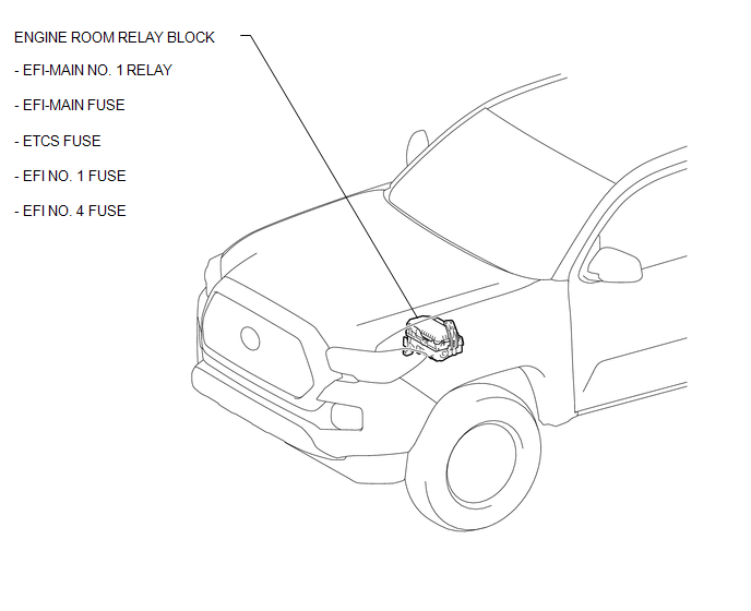
ILLUSTRATION
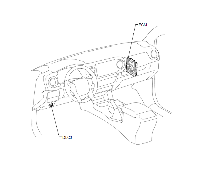
ILLUSTRATION
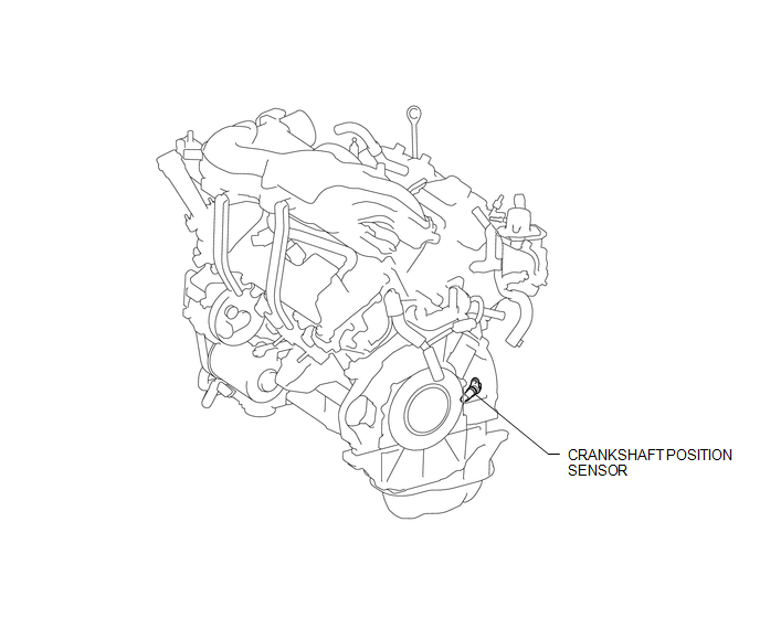
ILLUSTRATION
 Precaution
PRECAUTION
1. INITIALIZATION
NOTICE:
If the ECM is replaced, register the ECU communication ID for Engine
Immobiliser System (See page ).
Perform Registration (VIN registration) wh ...
 System Diagram
SYSTEM DIAGRAM
...
Other materials:
Installation
INSTALLATION
PROCEDURE
1. INSTALL VANE PUMP ASSEMBLY
(a) Install the vane pump assembly with the 2 bolts.
Torque:
21 N┬Àm {214 kgf┬Àcm, 15 ft┬Àlbf}
(b) Connect the ground wire with the bolt.
Torque:
8.5 N┬Àm {87 kgf┬Àcm, 75 in┬Àlbf}
2. CONNECT PRESSURE FEED TUBE ASSEMBLY
(a) Install a ne ...
Registration
REGISTRATION
PROCEDURE
1. DESCRIPTION OF CODE REGISTRATION
HINT:
Registering an ID code enables the entry and start function, wireless
door lock control function and engine immobiliser function to be operated.
Code registration is needed when the certification ECU (smart key E ...
System Description
SYSTEM DESCRIPTION
1. SYSTEM FUNCTION
Function
Outline
Push-button start function
When the key is brought into the vehicle and verified, this function
changes the power source or starts the engine when the engine switch and
brake pedal are ...
