Toyota Tacoma (2015-2018) Service Manual: Front Right Seat Heat Sensor Circuit (B14C0)
DESCRIPTION
Output to the front seat cushion heater assembly RH temperature sensor stops if one of the following occurs: 1) the temperature sensor is open or shorted; or 2) the temperature sensor is damaged and its output value does not change.
|
DTC Code |
DTC Detection Condition |
Trouble Area |
|---|---|---|
|
B14C0 |
Seat heater temperature sensor malfunction |
|
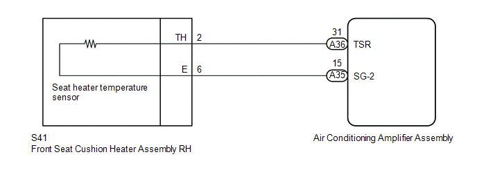
WIRING DIAGRAM
PROCEDURE
|
1. |
CLEAR DTC |
(a) Clear the DTCs (See page .gif) ).
).
|
.gif)
|
2. |
CHECK FOR DTC |
(a) Check for DTCs (See page ).
OK:
DTC B14C0 is not output.
| OK | .gif) |
USE SIMULATION METHOD TO CHECK |
|
|
3. |
READ VALUE USING TECHSTREAM |
(a) Connect the Techstream to the DLC3.
(b) Turn the ignition switch to ON.
(c) Turn the Techstream on.
(d) Enter the following menus: Body Electrical / Air Conditioner / Data List.
(e) Check the value(s) by referring to the table below.
Air Conditioner:
|
Tester Display |
Measurement Item/Range |
Normal Condition |
Diagnostic Note |
|---|---|---|---|
|
FR Seat Heater Temperature |
Front seat RH side seat heater temperature / min: -29.7°C or max: 59.55°C |
Within range from 36 to 42.2°C (96 to 108°F) |
Front seat heater is on |
OK:
The display is as specified in the normal condition column.
Result|
Result |
Proceed to |
|---|---|
|
NG |
A |
|
OK |
B |
| B | |
REPLACE AIR CONDITIONING AMPLIFIER ASSEMBLY |
|
|
4. |
INSPECT FRONT SEAT CUSHION HEATER ASSEMBLY RH |
(a) Remove the front seat cushion heater assembly RH (See page
).
(b) Inspect the front seat cushion heater assembly RH (See page
).
| NG | |
REPLACE FRONT SEAT CUSHION HEATER ASSEMBLY RH |
|
|
5. |
CHECK HARNESS AND CONNECTOR (AIR CONDITIONING AMPLIFIER ASSEMBLY - FRONT SEAT CUSHION HEATER ASSEMBLY RH) |
(a) Disconnect the A35 and A36 air conditioning amplifier assembly connector.
(b) Measure the resistance according to the value(s) in the table below.
Standard Resistance:
|
Tester Connection |
Condition |
Specified Condition |
|---|---|---|
|
A36-31 (TSR) - S41-2 (TH) |
Always |
Below 1 Ω |
|
A35-15 (SG-2) - S41-6 (E) |
Always |
Below 1 Ω |
|
A36-31 (TSR) - Body ground |
Always |
10 kΩ or higher |
|
A35-15 (SG-2)) - Body ground |
Always |
10 kΩ or higher |
| OK | |
REPLACE AIR CONDITIONING AMPLIFIER ASSEMBLY |
| NG | |
REPAIR OR REPLACE HARNESS OR CONNECTOR |
 Diagnostic Trouble Code Chart
DIAGNOSTIC TROUBLE CODE CHART
HINT:
If a trouble code is displayed during the DTC check, inspect the trouble areas
listed for that code. For details of the code, refer to the "See page" ...
 Front Left Seat Heat Sensor Circuit (B14C1)
DESCRIPTION
Output to the front seat cushion heater assembly LH temperature sensor stops
if one of the following occurs: 1) the temperature sensor is open or shorted; or
2) the temperature sensor ...
Other materials:
Detachable pole antenna
The antenna can be removed.
■ Removing the antenna
Place the included wrench around the antenna.
When not in use, the wrench is stored in glove box.
Loosen the antenna with the wrench and remove it.
■ Installing the antenna
Tighten the antenna by one hand until it will not t ...
Installation
INSTALLATION
CAUTION / NOTICE / HINT
CAUTION:
Be sure to perform this procedure with several people as the transfer assembly
is very heavy.
PROCEDURE
1. INSTALL TRANSFER CASE LOWER PROTECTOR
(a) Install the transfer case lower protector with the 4 bolts.
Torque:
18 N·m {184 kgf·cm, 13 f ...
Communication Error from VSC to ECM Invalid Serial Data Received (P163081)
DESCRIPTION
The skid control ECU (master cylinder solenoid)*1 or skid control ECU (brake
actuator assembly)*2 sends signals such as cruise control cancel signals and brake
demand response signals to the ECM when the dynamic radar cruise control system
is operating.
DTC No.
...
