Toyota Tacoma (2015-2018) Service Manual: Inspection
INSPECTION
PROCEDURE
1. INSPECT CAMSHAFT TIMING OIL CONTROL SOLENOID ASSEMBLY
(a) Check the operation.
|
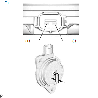
(1) Apply battery voltage between the terminals and check that the plunger operates. Text in Illustration
OK: The plunger extends outwards 5.9 mm (0.232 in.) or more. If the result is not as specified, replace the camshaft timing oil control solenoid assembly. |
|
 On-vehicle Inspection
ON-VEHICLE INSPECTION
PROCEDURE
1. INSPECT CAMSHAFT TIMING OIL CONTROL SOLENOID ASSEMBLY (for Intake Side)
(a) Connect the Techstream to the DLC3.
(b) Start the engine.
(c) Turn the Techstream on ...
 Removal
REMOVAL
PROCEDURE
1. REMOVE FRONT FENDER SEAL RH
HINT:
Use the same procedure as for the LH side (See page
).
2. REMOVE V-BANK COVER SUB-ASSEMBLY
3. REMOVE AIR CLEANER CAP AND HOSE
4. ...
Other materials:
Installation
INSTALLATION
PROCEDURE
1. INSTALL DIFFERENTIAL SIDE GEAR SHAFT OIL SEAL
(a) Using SST and a hammer, install a new oil seal.
SST: 09554-30011
(b) Coat the oil seal lip with MP grease.
2. INSTALL FRONT DRIVE SHAFT ASSEMBLY LH
Click here
3. INSTALL FRONT DRIVE SHAFT ASSEMBLY RH
HINT:
Use ...
VSC Buzzer Circuit
DESCRIPTION
The skid control ECU (master cylinder solenoid) is connected to the combination
meter via CAN communication.
The combination meter has a built-in VSC warning buzzer:
Sounds intermittently to inform the driver if the temperature of hydraulic
brake booster has increased exc ...
Problem Symptoms Table
PROBLEM SYMPTOMS TABLE
HINT:
Use the table below to help determine the cause of problem symptoms.
If multiple suspected areas are listed, the potential causes of the symptoms
are listed in order of probability in the "Suspected Area" column of the
table.
Check each ...
