Toyota Tacoma (2015-2018) Service Manual: Parking Brake Cable
Components
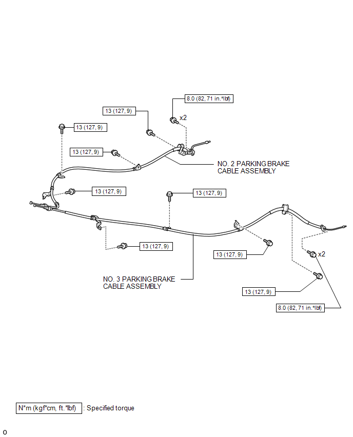
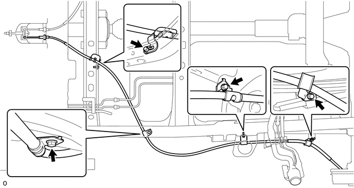
COMPONENTS
ILLUSTRATION
Removal
REMOVAL
PROCEDURE
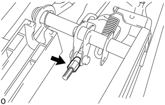
1. DISCONNECT NO. 2 PARKING BRAKE SHOE ASSEMBLY WITH PARKING BRAKE SHOE LEVER
(See page .gif) )
)
2. REMOVE VOLTAGE INVERTER ASSEMBLY
(See page )
3. REMOVE NO. 2 PARKING BRAKE CABLE ASSEMBLY
|
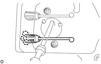
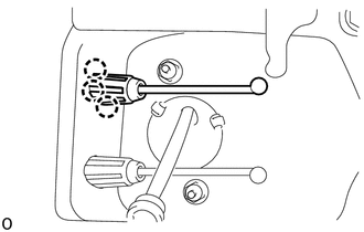
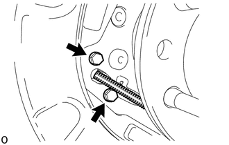
(a) Loosen the adjusting nut. |
|
|
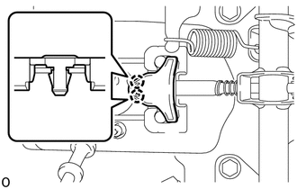
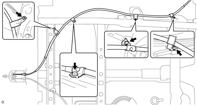
(b) Disengage the 2 claws to remove the parking cable end stopper. |
|
(c) Disconnect the No. 2 parking brake cable assembly from the No. 1 parking brake pull rod.
|
(d) Disengage the 3 claws of the No. 2 parking brake cable assembly and push the No. 2 parking brake cable assembly outside of vehicle slightly. |
|
|
(e) Remove the 2 bolts and disconnect the No. 2 parking brake cable assembly from the backing plate. |
|
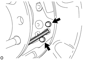
(f) Remove the 4 bolts and No. 2 parking brake cable assembly.
4. REMOVE NO. 3 PARKING BRAKE CABLE ASSEMBLY
|
(a) Loosen the adjusting nut. |
|
|
(b) Disengage the 2 claws to remove the parking cable end stopper. |
|
(c) Disconnect the No. 3 parking brake cable assembly from the No. 1 parking brake pull rod.
|
(d) Disengage the 3 claws of the No. 3 parking brake cable assembly and push the No. 3 parking brake cable assembly outside of vehicle slightly. |
|
|
(e) Remove the 2 bolts and disconnect the No. 3 parking brake cable assembly from the backing plate. |
|
(f) Remove the 4 bolts and No. 3 parking brake cable assembly.
Installation
INSTALLATION
PROCEDURE
1. INSTALL NO. 3 PARKING BRAKE CABLE ASSEMBLY
(a) Install the No. 3 parking cable assembly with the 4 bolts.
Torque:
13 N·m {127 kgf·cm, 9 ft·lbf}
(b) Attach the claws of the No. 3 parking brake cable assembly.
(c) Connect the No. 3 parking brake cable assembly to the No. 1 parking brake pull rod.
(d) Engage the 2 claws to install the parking brake cable end stopper.
(e) Install the No. 3 parking brake cable assembly to the backing plate with the 2 bolts.
Torque:
8.0 N·m {82 kgf·cm, 71 in·lbf}
2. INSTALL NO. 2 PARKING BRAKE CABLE ASSEMBLY
(a) Install the No. 2 parking brake cable assembly with the 4 bolts.
Torque:
13 N·m {127 kgf·cm, 9 ft·lbf}
(b) Attach the claws of the No. 2 parking brake cable assembly.
(c) Connect the No. 2 parking brake cable assembly to the No. 1 parking brake pull rod.
(d) Engage the 2 claws to install the parking brake cable end stopper.
(e) Install the No. 2 parking brake cable assembly to the backing plate with the 2 bolts.
Torque:
8.0 N·m {82 kgf·cm, 71 in·lbf}
3. CONNECT NO. 2 PARKING BRAKE SHOE ASSEMBLY WITH PARKING BRAKE SHOE LEVER
(See page .gif) )
)
4. INSPECT PARKING BRAKE LEVER TRAVEL
5. ADJUST PARKING BRAKE LEVER TRAVEL
6. INSTALL VOLTAGE INVERTER ASSEMBLY
(See page )
7. INSTALL REAR WHEEL
Torque:
113 N·m {1152 kgf·cm, 83 ft·lbf}
 Parking Brake
...
 Parking Brake Lever
Components
COMPONENTS
ILLUSTRATION
ILLUSTRATION
Installation
INSTALLATION
PROCEDURE
1. INSTALL PARKING BRAKE SWITCH ASSEMBLY
2. INSTALL PARKING BRAKE LEVER SUB-ASSEMBLY
(a) Install ...
Other materials:
Installation
INSTALLATION
PROCEDURE
1. INSPECT PROPELLER SHAFT WITH CENTER BEARING ASSEMBLY (with Grease Fitting)
Text in Illustration
*1
Grease Fitting
-
-
*a
View A
*b
Front Side
HINT:
When replacing t ...
Inspection
INSPECTION
PROCEDURE
1. INSPECT WINDSHIELD WIPER MOTOR ASSEMBLY
(a) Check the LO operation.
Text in Illustration
*a
Component without harness connected
(Windshield Wiper Motor Assembly)
(1) Apply battery voltage to the windshield wiper motor connector and ch ...
Occupant Classification System Malfunction (B1650/32)
DESCRIPTION
The occupant classification system circuit consists of the airbag sensor assembly
and the occupant classification system.
When the airbag sensor assembly receives signals from the occupant detection
ECU, it determines whether or not the instrument panel passenger without door airba ...
