Toyota Tacoma (2015-2018) Service Manual: Outer Mirror Switch
Inspection
INSPECTION
PROCEDURE
1. INSPECT OUTER MIRROR SWITCH ASSEMBLY
(a) Check the mirror select switch and mirror surface adjust switch.
|
(1) Turn the mirror select switch to the L position. Text in Illustration
|
|
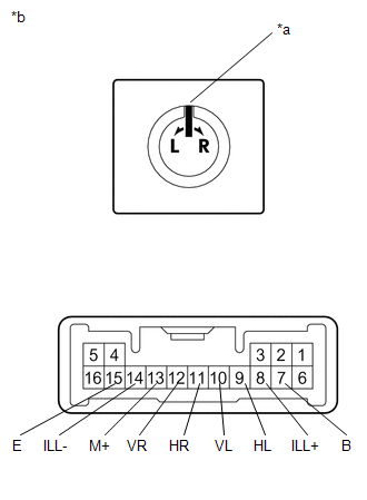
(2) Measure the resistance according to the value(s) in the table below.
Standard Resistance (for left side):
|
Tester Connection |
Condition |
Specified Condition |
|---|---|---|
|
10 (VL) - 7 (B) 13 (M+) - 15 (E) |
Up |
Below 1 Ω |
|
Off |
10 kΩ or higher |
|
|
10 (VL) - 15 (E) 13 (M+) - 7 (B) |
Down |
Below 1 Ω |
|
Off |
10 kΩ or higher |
|
|
9 (HL) - 7 (B) 13 (M+) - 15 (E) |
Left |
Below 1 Ω |
|
Off |
10 kΩ or higher |
|
|
9 (HL) - 15 (E) 13 (M+) - 7 (B) |
Right |
Below 1 Ω |
|
Off |
10 kΩ or higher |
(3) Turn the mirror select switch to the R position.
(4) Measure the resistance according to the value(s) in the table below.
Standard Resistance (for right side):
|
Tester Connection |
Condition |
Specified Condition |
|---|---|---|
|
12 (VR) - 7 (B) 13 (M+) - 15 (E) |
Up |
Below 1 Ω |
|
Off |
10 kΩ or higher |
|
|
12 (VR) - 15 (E) 13 (M+) - 7 (B) |
Down |
Below 1 Ω |
|
Off |
10 kΩ or higher |
|
|
11 (HR) - 7 (B) 13 (M+) - 15 (E) |
Left |
Below 1 Ω |
|
Off |
10 kΩ or higher |
|
|
11 (HR) - 15 (E) 13 (M+) - 7 (B) |
Right |
Below 1 Ω |
|
Off |
10 kΩ or higher |
If the result is not as specified, replace the outer mirror switch assembly.
(b) Check the switch illumination.
(1) Apply battery voltage between the terminals of the light and check the operation of the light.
OK:
|
Measurement Connection |
Specified Condition |
|---|---|
|
Battery positive (+) → Terminal 8 (ILL+) |
Light comes on |
|
Battery negative (-) → Terminal 14 (ILL-) |
If the result is not as specified, replace the outer mirror switch assembly.
 Inner Rear View Mirror
Components
COMPONENTS
ILLUSTRATION
ILLUSTRATION
Calibration
CALIBRATION
1. SELECT COMPASS DISPLAY MODE
(a) The compass switch allows you to select the Display or Non-display mode of
t ...

Other materials:
Dtc Check / Clear
DTC CHECK / CLEAR
1. CHECK DTC (for TIRE PRESSURE WARNING ECU AND RECEIVER) (USING TECHSTREAM)
(a) Turn the ignition switch off.
(b) Connect the Techstream to the DLC3.
(c) Turn the ignition switch to ON.
(d) Turn the Techstream on.
(e) Enter the following menus: Chassis / Tire Pressure Monito ...
Vehicle Speed Signal Circuit between Radio Receiver and Combination Meter
DESCRIPTION
for Audio Function:
The radio and display receiver assembly receives a vehicle speed signal
from the combination meter assembly and sends the signal to radio and display
receiver assembly.
for Automatic Sound Levelizer (ASL):
This circuit is necessary fo ...
System Description
SYSTEM DESCRIPTION
1. GENERAL
(a) To assist the driver with parking the vehicle by displaying an image of the
area behind the vehicle, this system has a rear television camera assembly mounted
on the tailgate. The system displays the image on the multi-display.
(b) This system consists of the ...
