Toyota Tacoma (2015-2018) Service Manual: Inner Rear View Mirror
Components
COMPONENTS
ILLUSTRATION
ILLUSTRATION
Calibration
CALIBRATION
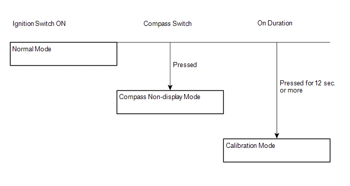
1. SELECT COMPASS DISPLAY MODE
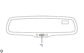
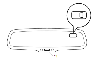
(a) The compass switch allows you to select the Display or Non-display mode of the compass.
|
*1 |
Compass Switch / EC Control Switch |
2. PERFORM CALIBRATION
(a) As each vehicle has its own magnetic field, calibration should be performed for each individual vehicle. This compass function is used when storing the record of the vehicle's magnetic field.
3. WHEN COMPASS IS MAGNETIZED
(a) A compass could be magnetized during shipping by vessels or freight cars. Therefore, make sure to perform calibration and ensure that calibration is performed properly before delivery. If this cannot be done (cannot be completed in spite of driving around several times), it may be caused by magnetization. Demagnetize the vehicle using a demagnetizer and perform calibration again.
4. SET COMPASS
5. CALIBRATION SETTING MODE
(a) Pressing the compass switch for 12 seconds or more in the normal mode will activate the calibration setting mode. "C" is displayed on the compass display.
|
*1 |
Compass Switch |
(b) Drive the vehicle at a slow speed of 8 km/h (5 mph) or less in a circular direction.
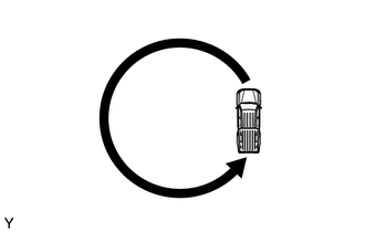
(c) Driving in a circle 1 to 3 times will display the azimuthal direction on the display, completing the calibration.
HINT:
After the calibration is completed, it is not necessary to perform the above procedures unless the magnetic field strength is drastically changed. If this happens, the azimuthal display will be changed to "C".
Inspection
INSPECTION
PROCEDURE
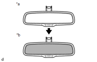
1. INSPECT INNER REAR VIEW MIRROR ASSEMBLY (w/ EC Mirror)
(a) Check operation of the electrochromic inner rear view mirror.
|
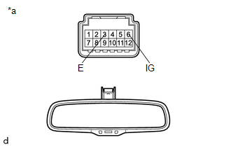
(1) Connect the positive (+) lead of the battery to terminal 6 (IG) and negative (-) lead to terminal 3 (E). Text in Illustration
|
|
|
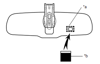
(2) Attach black-colored tape to the forward sensor to prevent it from sensing light. Text in Illustration
|
|
|
(3) Shine an electric light on the mirror. Check that the mirror surface changes from bright to dark. Text in Illustration
HINT: When the environment is very bright, the antiglare operation may occur immediately after the tape is applied. If the result is not as specified, replace the mirror assembly. |
|
Installation
INSTALLATION
PROCEDURE
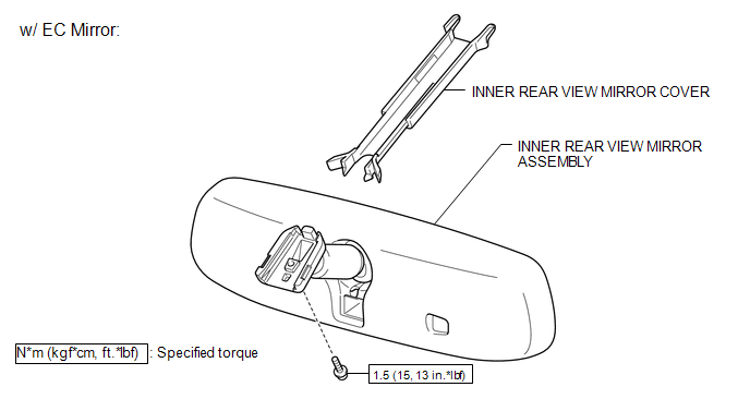
1. INSTALL INNER REAR VIEW MIRROR ASSEMBLY (w/ EC Mirror)
(a) Using a T20 "TORX" socket wrench, install the inner rear view mirror assembly with the screw.
Torque:
1.5 N·m {15 kgf·cm, 13 in·lbf}
(b) Connect the connector.
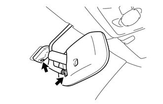
2. INSTALL INNER REAR VIEW MIRROR COVER (w/ EC Mirror)
|
(a) Slide the inner rear view mirror cover in the direction indicated by the arrow in the illustration to engage the 2 claws to the roof headlining to install the inner rear view mirror cover. |
|

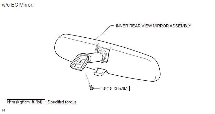
3. INSTALL INNER REAR VIEW MIRROR ASSEMBLY (w/o EC Mirror)
(a) Using a T20 "TORX" socket wrench, install the inner rear view mirror assembly with the screw.
Torque:
1.5 N·m {15 kgf·cm, 13 in·lbf}
Removal
REMOVAL
PROCEDURE
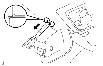
1. REMOVE INNER REAR VIEW MIRROR COVER (w/ EC Mirror)
|
(a) Slide the inner rear view mirror cover in the direction indicated by the arrow in the illustration to disengage the 2 claws from the roof headlining to remove the inner rear view mirror cover. |
|
2. REMOVE INNER REAR VIEW MIRROR ASSEMBLY (w/ EC Mirror)
|
(a) Disconnect the connector. |
|
(b) Using a T20 "TORX" socket wrench, remove the screw and inner rear view mirror assembly.
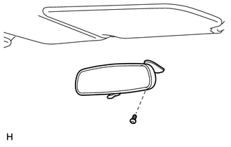
3. REMOVE INNER REAR VIEW MIRROR ASSEMBLY (w/o EC Mirror)
|
(a) Using a T20 "TORX" socket wrench, remove the screw and inner rear view mirror assembly. |
|
 Mirror
...
 Outer Mirror Switch
Inspection
INSPECTION
PROCEDURE
1. INSPECT OUTER MIRROR SWITCH ASSEMBLY
(a) Check the mirror select switch and mirror surface adjust switch.
(1) Turn the mirror select switch to the ...
Other materials:
Reassembly
REASSEMBLY
PROCEDURE
1. INSTALL FRONT PROPELLER SHAFT UNIVERSAL JOINT SPIDER BEARING
(a) Apply MP grease to a new spider and spider bearing.
(b) Fit the spider into the flange yoke.
(c) Measure dimension A between the snap ring grooves.
...
Front Airbag Sensor LH Circuit Malfunction (B1615/14)
DESCRIPTION
The front airbag sensor LH consists of parts such as the diagnostic circuit and
the frontal detection sensor.
When the airbag sensor assembly receives signals from the frontal deceleration
sensor, it determines whether or not the SRS should be activated.
DTC B1615/14 is set when a ...
Check Bus 5 Line for Short to GND
DESCRIPTION
There may be a short circuit between one of the CAN bus lines and GND when there
is no resistance between terminal 15 (CA5H) of the central gateway ECU (network
gateway ECU) and terminal 4 (CG) of the DLC3, or terminal 16 (CA5L) of the central
gateway ECU (network gateway ECU) and ...
