Toyota Tacoma (2015-2018) Service Manual: Operation Check
OPERATION CHECK
1. BLIND SPOT MONITOR BEAM AXIS INSPECTION
(a) Procedure to enter Test Mode
(1) Connect the Techstream to the DLC3.
(2) Turn the ignition switch to ON.
(3) Turn the blind spot monitor main switch assembly (warning canceling switch assembly) on.
(4) Turn the Techstream on.
(5) Switch the blind spot monitor sensor to Test Mode using the Techstream. Enter the following menus: Body Electrical / Blind Spot Monitor Master or Blind Spot Monitor Slave / Utility / BSM Master beam axis inspection or BSM Slave beam axis inspection.
(6) Finish Test Mode.
2. BLIND SPOT MONITOR BEAM AXIS CONFIRMATION
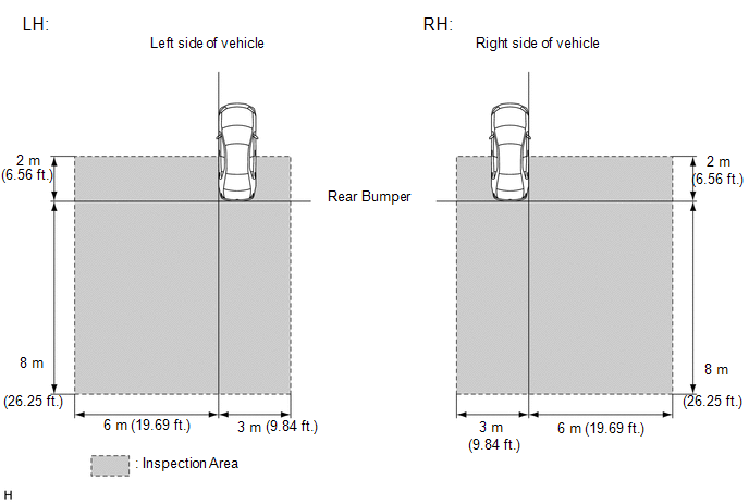
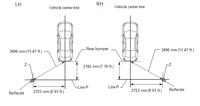
(a) When performing the blind spot monitor beam axis confirmation, move the vehicle to a place where the space shown in the illustration can be secured.
NOTICE:
- Perform this inspection on level ground.
- Make sure that there are no metal objects around the vehicle or on the ground.
- Unload the vehicle before beginning the inspection.
- Confirm that the tire pressure is correct before beginning the inspection.
- Do not place an object other than the reflector (such as a large metallic object) in or allow people to enter the inspection area (W 9 m (29.53 ft.) x L 10 m (32.81 ft.) x H 4 m (13.13 ft.)) shown in the illustration.
- Check that DTC C1ABB and DTC C1ABC are not output.
(b) Place the reflector.
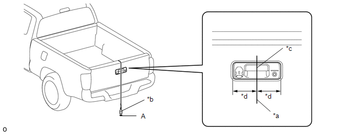
(1) Hang a weight with a pointed tip from the center of the tail gate handle assembly, and mark the rear center point of the vehicle (point A) on the ground.
|
*a |
String |
*b |
Weight |
|
*c |
Center point |
*d |
Equal Distance to Center |
HINT:
Lightly flick the string with your fingers several times to confirm that the string is perpendicular to the ground.
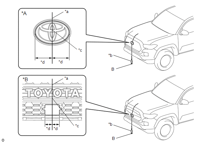
(2) Hang a weight with a pointed tip from the center of the radiator grille emblem, and mark the front center point of the vehicle (point B) on the ground (placement position).
|
*A |
for Type A or Type B |
*B |
for Type C |
|
*a |
String |
*b |
Weight |
|
*c |
Center point |
*d |
Equal Distance to Center |
HINT:
Lightly flick the string with your fingers several times to confirm that the string is perpendicular to the ground.
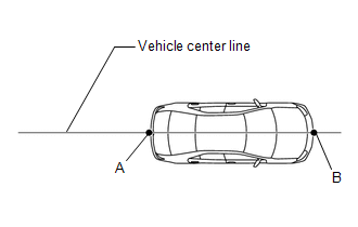
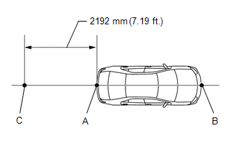
(3) Draw a vehicle center line so that it passes through mark (A) and (B) (front and rear center points).
(4) Mark the position on the center line 2192 mm (7.19 ft.) behind the rear bumper. (Mark (C))
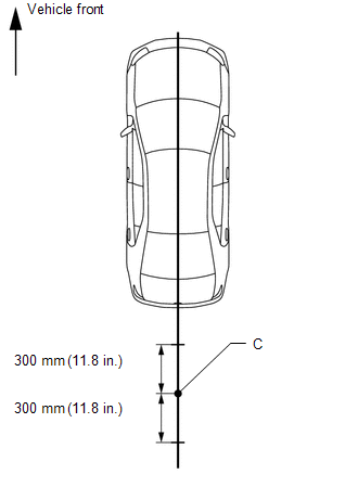
(5) Prepare 2 pieces of string of 600 mm (1.97 ft.) in length and secure the end of each string at a point 300 mm (11.8 in.) from mark (C) as shown in the illustration.
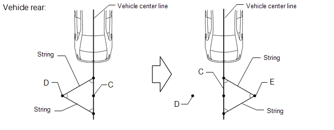
(6) Pull the end of each string and mark the position where each string meets on both the left and right side (marks (D) and (E)).
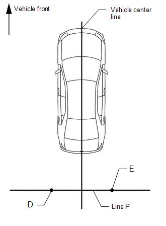
(7) Draw a line (P) so that it passes through mark (D) and (E) and is perpendicular to the vehicle center line.
(8) Set the reflector at the position (Z) shown in the illustration below.
SST: 09870-60000
09870-60010
SST: 09870-60040
NOTICE:
- Set the reflector so that its center is 599 mm (1.97 ft.) above the
ground.
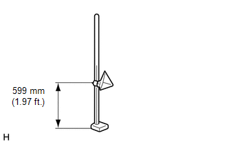
- The center of triangular pyramid is the reference point for the setting
position and angle.
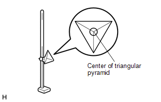
- Set the reflector as shown in the illustration so that its center of triangular pyramid faces the blind spot monitor sensor.
- Perform the operation as precisely as possible.
(c) Perform the blind spot monitor beam axis display.
(1) Connect the Techstream to the DLC3.
(2) Turn the ignition switch to ON.
(3) Turn the blind spot monitor main switch assembly (warning canceling switch assembly) on.
(4) Turn the Techstream on.
(5) Enter the following menus: Body Electrical / Blind spot monitor Master or Blind spot monitor Slave / Utility / BSM Master beam axis display or BSM Slave beam axis display.
(6) Check the results displayed for the BSM beam axis display.
Allowable Range:
|
Item |
Blind Spot Monitor Sensor LH (Master) |
Blind Spot Monitor Sensor RH (Slave) |
|---|---|---|
|
Angle |
-3.6 to +3.6° |
-3.6 to +3.6° |
HINT:
If the results are outside the allowable range, it is possible that the reflector position is incorrect, there is a metallic object near the inspection area or the blind spot monitor sensor installation condition is abnormal, so check the reflector positioning, the inspection area and the blind spot monitor sensor installation condition, and perform the inspection again.
(7) Perform the blind spot monitor beam axis adjustment using the Techstream. Enter the following menus: Body Electrical / Blind spot monitor Master or Blind spot monitor Slave / Utility / BSM Master beam axis adjustment or BSM Slave beam axis adjustment.
HINT:
When values on the axis display are in the allowable range, performing this adjustment compensates the values to the normal value.
3. BLIND SPOT MONITOR INSTALLATION CONDITION INSPECTION
NOTICE:
- Perform this inspection on level ground.
- Unload the vehicle before beginning the inspection.
- Confirm that the tire pressure is correct before beginning the inspection.
(a) Remove the rear bumper assembly.
- w/ Towing Package (See page
.gif) )
) - w/o Towing Package (See page )
(b) Remove the rear bumper extension LH.
- w/ Towing Package (See page )
- w/o Towing Package (See page )
HINT:
Remove the rear bumper extension from the side that is being inspected.
(c) Remove the rear bumper extension RH.
- w/ Towing Package (See page )
- w/o Towing Package (See page )
HINT:
Remove the rear bumper extension from the side that is being inspected.
(d) Install the rear bumper assembly.
- w/ Towing Package (See page )
- w/o Towing Package (See page )
HINT:
When installing the rear bumper, install it with the rear bumper extension removed.
(e) Attach a jig similar to the one shown in the illustration to the outward facing surface of the blind spot monitor sensor and check that the blind spot monitor sensor is perpendicular to the floor surface or within the allowable range.
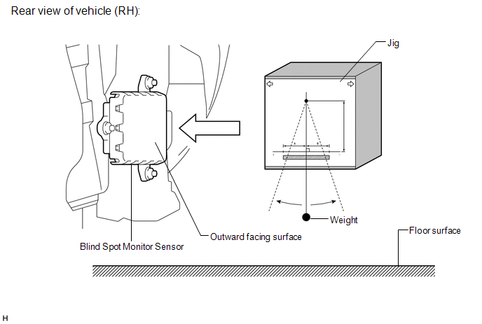
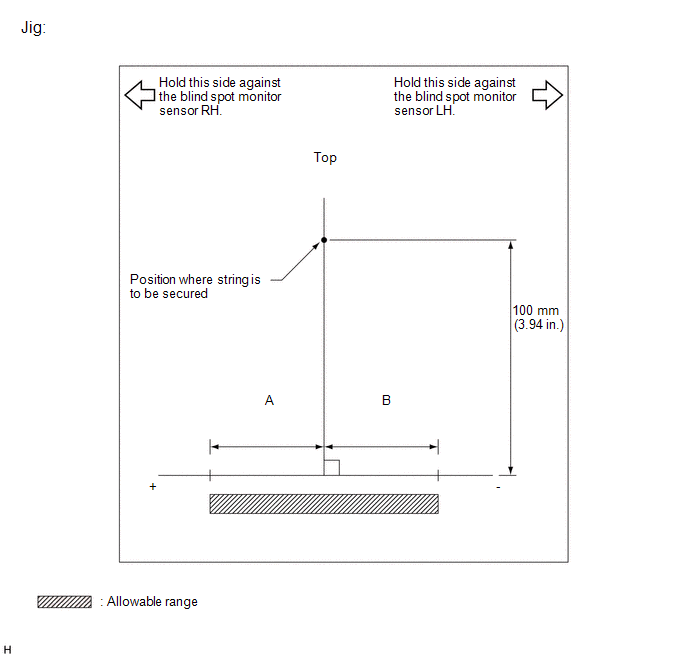 Standard
|
A |
B |
|
|---|---|---|
|
Blind spot monitor sensor RH |
8 mm (0.315 in.) |
-8 mm (-0.315 in.) |
|
Blind spot monitor sensor LH |
8 mm (0.315 in.) |
-8 mm (-0.315 in.) |
(f) Using the sensor installation stud bolt center lines as a reference, check that the stud bolts are as shown in the illustration.
Standard:
|
Dimension |
Specified Value |
|---|---|
|
y |
75 to 84 mm (2.95 to 3.31 in.) |
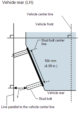
HINT:
If the results are not as specified, it is possible that the blind spot monitor sensor installation area (frame, stud bolt) is deformed, so make corrections as necessary.
 How To Proceed With Troubleshooting
CAUTION / NOTICE / HINT
HINT:
Use the following procedure to troubleshoot the blind spot monitor system.
*: Use the Techstream.
PROCEDURE
1.
VEHICLE BRO ...
 Problem Symptoms Table
PROBLEM SYMPTOMS TABLE
HINT:
Use the table below to help determine the cause of problem symptoms. If multiple
suspected areas are listed, the potential causes of the symptoms are listed in order
...
Other materials:
Vacuum Warning Switch
Components
COMPONENTS
ILLUSTRATION
On-vehicle Inspection
ON-VEHICLE INSPECTION
PROCEDURE
1. INSPECT BRAKE FLUID LEVEL IN RESERVOIR
2. INSPECT BRAKE BOOSTER ASSEMBLY
3. INSPECT VACUUM WARNING SWITCH ASSEMBLY
(a) Start the engine and stop it after 1 or 2 minutes.
(b) Disconnect the ...
Installation
INSTALLATION
PROCEDURE
1. INSTALL POWER STEERING LINK
(a) Insert the power steering link into the vehicle in the order shown in the
illustration.
Install in this Direction (1)
Install in this Direction (2)
(b) Temporarily install the po ...
Installation
INSTALLATION
PROCEDURE
1. SET NO. 1 CYLINDER TO TDC/COMPRESSION
2. INSTALL CAMSHAFT TIMING GEAR BOLT
NOTICE:
There are different types of camshaft timing gear bolts. Make sure to check the
identification mark to determine the tightening torque.
*a
Identification Ma ...
