Toyota Tacoma (2015-2018) Service Manual: Open in Stop Light Switch Circuit (C1425)
DESCRIPTION
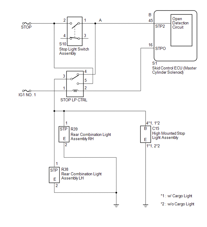
The skid control ECU (master cylinder solenoid) inputs stop light switch signals and the brake operation condition.
The skid control ECU (master cylinder solenoid) has an open detection circuit, which outputs this DTC when detecting an open circuit in the stop light input line or the ground line of the stop light circuit with the stop light switch off (brake pedal not depressed).
|
DTC Code |
DTC Detection Condition |
Trouble Area |
|---|---|---|
|
C1425 |
When the IG1 terminal voltage is between 9.5 and 17.4 V and the skid control ECU (master cylinder solenoid) STPO terminal output is off, an open in the stop light switch circuit (A to B, A to body ground) continues for 3 seconds or more. |
|
WIRING DIAGRAM
CAUTION / NOTICE / HINT
NOTICE:
When replacing the master cylinder solenoid, perform calibration (See page
.gif) ).
).
PROCEDURE
|
1. |
CHECK STOP LIGHT SWITCH OPERATION |
| NG | .gif) |
GO TO STEP 5 |
|
.gif)
|
2. |
READ VALUE USING TECHSTREAM (STOP LIGHT SW) |
(a) Turn the ignition switch off.
(b) Connect the Techstream to the DLC3.
(c) Turn the ignition switch to ON.
(d) Turn the Techstream on.
(e) Enter the following menus: Chassis / ABS/VSC/TRAC / Data List.
ABS/VSC/TRAC|
Tester Display |
Measurement Item/Range |
Normal Condition |
Diagnostic Note |
|---|---|---|---|
|
Stop Light SW |
Stop light switch/ ON or OFF |
ON: Brake pedal depressed OFF: Brake pedal released |
- |
(f) Check that the stop light condition observed on the Techstream changes according to brake pedal operation.
Standard:
The Techstream displays ON or OFF according to brake pedal operation.
| OK | |
USE SIMULATION METHOD TO CHECK |
|
|
3. |
CHECK HARNESS AND CONNECTOR (STP2 TERMINAL) |
| NG | |
REPAIR OR REPLACE HARNESS OR CONNECTOR (STP2 CIRCUIT) |
|
|
4. |
RECONFIRM DTC |
(a) Clear the DTCs (See page
).
(b) Turn the ignition switch off.
(c) Start the engine.
(d) Depress the brake pedal several times to test the stop light circuit.
(e) Check if the same DTC is output (See page
).
|
Result |
Proceed to |
|---|---|
|
DTC is not output |
A |
|
DTC is output |
B |
| A | |
USE SIMULATION METHOD TO CHECK |
| B | |
REPLACE MASTER CYLINDER SOLENOID |
|
5. |
CHECK HARNESS AND CONNECTOR (POWER SOURCE TERMINAL) |
| NG | |
REPAIR OR REPLACE HARNESS OR CONNECTOR (POWER SOURCE CIRCUIT) |
|
|
6. |
INSPECT STOP LIGHT SWITCH ASSEMBLY |
| NG | |
REPLACE STOP LIGHT SWITCH ASSEMBLY |
|
|
7. |
CHECK HARNESS AND CONNECTOR (STOP LIGHT SWITCH ASSEMBLY - STOP LP CTRL RELAY) |
| NG | |
REPAIR OR REPLACE HARNESS OR CONNECTOR |
|
|
8. |
INSPECT STOP LP CTRL RELAY |
| NG | |
REPLACE STOP LP CTRL RELAY |
|
|
9. |
CHECK HARNESS AND CONNECTOR (REAR COMBINATION LIGHT ASSEMBLY, HIGH MOUNTED STOP LIGHT ASSEMBLY - STOP LP CTRL RELAY) |
| A | |
REPAIR OR REPLACE HARNESS OR CONNECTOR |
| C | |
GO TO STEP 11 |
|
|
10. |
INSPECT REAR COMBINATION LIGHT ASSEMBLY |
| OK | |
USE SIMULATION METHOD TO CHECK |
| NG | |
REPLACE REAR COMBINATION LIGHT ASSEMBLY |
|
11. |
INSPECT CENTER STOP LIGHT BULB |
| OK | |
USE SIMULATION METHOD TO CHECK |
| NG | |
REPLACE CENTER STOP LIGHT BULB |
 Acceleration Sensor Malfunction (C1420)
DESCRIPTION
Refer to DTCs C1419 and C1435 (See page ).
DTC Code
DTC Detection Condition
Trouble Area
C1420
After the difference between ...
 Steering Angle Sensor Power Source Voltage Malfunction (C1432)
DESCRIPTION
Steering angle sensor (spiral cable with sensor sub-assembly) signals are sent
to the skid control ECU (master cylinder solenoid) via the CAN communication system.
When there is a mal ...
Other materials:
Zero Point Calibration of Yaw Rate Sensor Undone (C1210,C1336)
DESCRIPTION
The skid control ECU (master cylinder solenoid) receives signals from the yaw
rate and acceleration (airbag sensor assembly) via the CAN communication system.
The airbag sensor assembly has a built-in yaw rate and acceleration sensor and
detects the vehicle's condition using 2 ...
Brake Warning Light does not Come ON
DESCRIPTION
The skid control ECU (brake actuator assembly) is connected to the combination
meter assembly via CAN communication.
WIRING DIAGRAM
Refer to Brake Warning Light Remains ON (See page
).
CAUTION / NOTICE / HINT
NOTICE:
When replacing the skid control ECU (brake actuator assembly) ...
Interior Light Auto Cut Circuit
DESCRIPTION
When the battery saving control operates, the main body ECU (multiplex network
body ECU) controls the operation of the DOME CUT relay, that is built in to the
driver side junction block, to turn off the interior lights.
WIRING DIAGRAM
CAUTION / NOTICE / HINT
NOTICE:
In ...
