Toyota Tacoma (2015-2018) Service Manual: On-vehicle Inspection
ON-VEHICLE INSPECTION
PROCEDURE
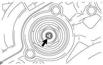
1. INSPECT CAMSHAFT TIMING GEAR BOLT
(a) Remove the camshaft timing oil control solenoid assembly (See page
.gif) ).
).
|
(b) Check that the plunger strokes when the plunger in the center of the camshaft timing gear bolt is pressed. Standard stroke: 4.5 mm (0.177 in.) or more HINT: When pressing the plunger, there is a stepped feeling but this is not a malfunction. If the result is not as specified, replace the camshaft timing gear bolt. |
|
(c) Install the camshaft timing oil control solenoid assembly (See page
).
 Components
COMPONENTS
ILLUSTRATION
...
 Removal
REMOVAL
CAUTION / NOTICE / HINT
NOTICE:
If one of the camshaft timing gear bolts is already removed, do not remove any
other camshaft timing gear bolts.
PROCEDURE
1. REMOVE NO. 2 ENGINE UNDER C ...
Other materials:
Removal
REMOVAL
PROCEDURE
1. REMOVE NO. 2 ENGINE UNDER COVER SUB-ASSEMBLY (w/ Off Road Package)
2. REMOVE NO. 1 ENGINE UNDER COVER SUB-ASSEMBLY
3. DRAIN ENGINE COOLANT
4. REMOVE RADIATOR GRILLE
(See page )
5. REMOVE EXHAUST MANIFOLD SUB-ASSEMBLY RH
(See page )
6. REMOVE NO. 2 OIL COOLER INLET ...
Replacement
REPLACEMENT
PROCEDURE
1. REPLACE STRAIGHT PIN
NOTICE:
It is not necessary to remove the straight pin unless it is being replaced.
(a) Using a plastic-faced hammer, tap in new straight pins to the cylinder block.
Text in Illustration
*A
Front Side
*B
...
Other System Malfunction (C1A63)
DESCRIPTION
The millimeter wave radar sensor assembly receives accelerator pedal position
sensor signals from the ECM to determine if the accelerator pedal is being depressed.
If the ECM detects a malfunction in the accelerator pedal position sensor or SFI
system, the millimeter wave radar se ...
