Toyota Tacoma (2015-2018) Service Manual: Components
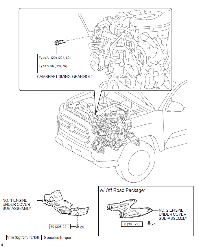
COMPONENTS
ILLUSTRATION

 On-vehicle Inspection
ON-VEHICLE INSPECTION
PROCEDURE
1. INSPECT CAMSHAFT TIMING GEAR BOLT
(a) Remove the camshaft timing oil control solenoid assembly (See page
).
(b) Check that the plunger strokes when ...
Other materials:
Transfer Case Front Oil Seal
Components
COMPONENTS
ILLUSTRATION
Replacement
REPLACEMENT
PROCEDURE
1. DRAIN TRANSFER OIL
2. SUPPORT TRANSMISSION ASSEMBLY
3. REMOVE NO. 3 FRAME CROSSMEMBER SUB-ASSEMBLY
4. REMOVE TRANSFER CASE LOWER PROTECTOR
5. REMOVE FRONT PROPELLER SHAFT ASSEMBLY
(See page )
6. ...
Installation
INSTALLATION
CAUTION / NOTICE / HINT
HINT:
Perform "Inspection After Repairs" after replacing the fuel injector assembly
(See page ).
PROCEDURE
1. INSTALL FUEL INJECTOR ASSEMBLY
HINT:
Perform "Inspection After Repairs" after replacing the fuel injector assembly
(See p ...
Installation
INSTALLATION
PROCEDURE
1. INSTALL TRANSMISSION WIRE
(a) Coat 2 new O-rings with ATF, and install them to the 2 temperature sensors.
(b) Coat a new O-ring with ATF, and install it to the transmission wire.
(c) Install the transmission wire to the automatic transmission case sub-assembly
with t ...
