Toyota Tacoma (2015-2018) Service Manual: On-vehicle Inspection
ON-VEHICLE INSPECTION
PROCEDURE
1. INSPECT GARAGE DOOR OPENER
|
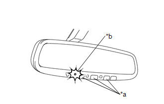
(a) Press each switch and check that the red LED turns on. If one or
more of the switches does not turn on the LED, confirm normal operation
of the fuse and wire harness. If the fuse and wire harness are malfunctioning,
replace them. If not, replace the garage door opener (inner rear view mirror
assembly) (See page
|
|
.gif)
2. INSPECT GARAGE DOOR OPENER REGISTRATION AND TRANSMITTING
HINT:
Use the "HomeLink" tester and a tester transmitter for this test. First erase the customer's transmitter code, and then register the tester transmitter code.
|
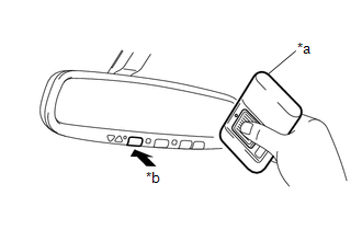
(a) Check if the test transmitter code was successfully registered. Text in Illustration
HINT: If the code cannot be registered, replace the garage door opener (inner
rear view mirror assembly) (See page |
|
|
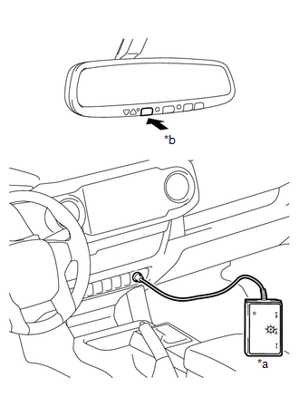
(b) Press the garage door opener switch that was registered to the tester transmitter. Check if the "HomeLink" tester's green LED illuminates. Text in Illustration
HINT: If the green LED does not illuminate, replace the garage door opener
(inner rear view mirror assembly) (See page
|
|
(c) When the inspection is complete, reregister the customer's transmitter code(s) again.
HINT:
- Registration of codes for the customer's transmitters may not be possible in the service facility if the customer's transmitters are not available or if any of the buttons are used for rolling code-type systems.
- Refer to the Owner's Manual for additional information about registration (programming) of transmitter codes.
 Registration
REGISTRATION
PROCEDURE
1. REGISTER TRANSMITTER CODE
HINT:
The vehicle's garage door opener records transmitter codes for systems
such as garage doors, gates, entry gates, door lock ...

Other materials:
Transponder Key Ecu
Components
COMPONENTS
ILLUSTRATION
Installation
INSTALLATION
PROCEDURE
1. INSTALL TRANSPONDER KEY ECU
(a) Engage the 2 guides to move the transponder key ECU in the direction
of the arrow to install the transponder key ECU.
2. IN ...
Bottle holders
Front
Front console box (Separated type
front seat)
Rear (Double Cab models)
■Bottle holders
Depending on their size or shape, some bottles may not fit in the holders.
NOTICE
■Items that should not be stowed in the bottle holders
Put the cap on before stowing a bottle. Do ...
Stereo Component Amplifier Disconnected (B15D3)
DESCRIPTION
The navigation receiver assembly and stereo component amplifier assembly are
connected by the AVC-LAN communication line.
When an AVC-LAN communication error occurs between the navigation receiver assembly
and stereo component amplifier assembly, this DTC will be stored.
...
