Toyota Tacoma (2015-2018) Service Manual: Main Switch Illumination Circuit
DESCRIPTION
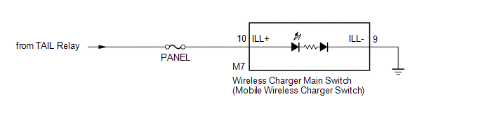
When the light control switch is turned to the tail or head position, this circuit sends an illumination signal to the wireless charger main switch (mobile wireless charger switch). Based on this signal, the wireless charger main switch (mobile wireless charger switch) is illuminated.
WIRING DIAGRAM
CAUTION / NOTICE / HINT
NOTICE:
Inspect the fuses for circuits related to this system before performing the following inspection procedure.
PROCEDURE
|
1. |
CHECK HARNESS AND CONNECTOR (ILLUMINATION SIGNAL) |
(a) Disconnect the M7 wireless charger main switch (mobile wireless charger switch) connector.
(b) Measure the voltage according to the value(s) in the table below.
Standard Voltage:
|
Tester Connection |
Switch Condition |
Specified Condition |
|---|---|---|
|
M7-10 (ILL+) - Body ground |
Light control switch in tail or head position |
11 to 14 V |
| NG | .gif) |
REPAIR OR REPLACE HARNESS OR CONNECTOR |
|
.gif)
|
2. |
CHECK HARNESS AND CONNECTOR (WIRELESS CHARGER MAIN SWITCH - BODY GROUND) |
(a) Disconnect the M7 wireless charger main switch (mobile wireless charger switch) connector.
(b) Measure the resistance according to the value(s) in the table below.
Standard Resistance:
|
Tester Connection |
Condition |
Specified Condition |
|---|---|---|
|
M7-9 (ILL-) - Body ground |
Always |
Below 1 Ω |
| OK | |
PROCEED TO NEXT SUSPECTED AREA SHOWN IN PROBLEM SYMPTOMS TABLE |
| NG | |
REPAIR OR REPLACE HARNESS OR CONNECTOR |
 Wireless Charger Illumination Circuit
DESCRIPTION
When the light control switch is turned to the tail or head position, this circuit
sends an illumination signal to the mobile wireless charger cradle assembly. Based
on this signal, t ...
 Pre-collision
...
Other materials:
Fuel Pressure Sensor
Components
COMPONENTS
ILLUSTRATION
Inspection
INSPECTION
PROCEDURE
1. INSPECT FUEL DELIVERY PIPE SUB-ASSEMBLY (FUEL PRESSURE SENSOR)
NOTICE:
Do not remove the fuel pressure sensor from the fuel delivery pipe sub-assembly.
If a fuel pressure sensor is removed, replace the ...
Brake Signal Malfunction (B2284)
DESCRIPTION
This DTC is stored when the brake signal sent via direct line and the brake signal
sent via CAN communication do not match.
HINT:
When the cable is disconnected and reconnected to the negative (-) battery terminal,
the power source mode returns to the state it was in before the ca ...
Air Inlet Damper Position Sensor Circuit (B1432/32)
DESCRIPTION
This sensor detects the position of the air inlet damper and sends the appropriate
signals to the air conditioning amplifier assembly. The position sensor is built
into the No. 1 air conditioning servo assembly (fresh/recirculation damper).
DTC No.
DTC Detecti ...
