Toyota Tacoma (2005ŌĆō2015) Owners Manual: Luggage compartment
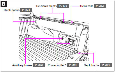
*: If equipped
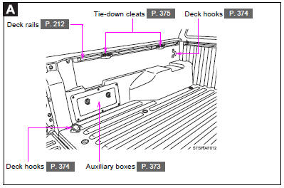
 Luggage compartment
*: If equipped ...

Other materials:
Front Right Seat Heat Sensor Circuit (B14C0)
DESCRIPTION
Output to the front seat cushion heater assembly RH temperature sensor stops
if one of the following occurs: 1) the temperature sensor is open or shorted; or
2) the temperature sensor is damaged and its output value does not change.
DTC Code
DTC Detection Cond ...
Sound Signal Circuit between Radio Receiver and Stereo Component Amplifier
DESCRIPTION
The navigation receiver assembly sends a sound signal to the stereo component
amplifier assembly via this circuit.
The sound signal that has been sent is amplified by the stereo component amplifier
assembly, and then is sent to the speakers.
If there is an open or short in the cir ...
Terminals Of Ecu
TERMINALS OF ECU
1. CLEARANCE WARNING ECU ASSEMBLY
(a) Disconnect the C30 connector from the clearance warning ECU assembly.
(b) Measure the voltage and resistance according to the value(s) in the table
below.
Terminal No. (Symbol)
Wiring Color
Terminal Descr ...
