Toyota Tacoma (2005ŌĆō2015) Owners Manual: Luggage compartment
*: If equipped
 Instrument panel
*1: 4WD models only
*2: If equipped
*3: Vehicles with a manual transmission
*: Refer to ŌĆ£NAVIGATION SYSTEM OWNERŌĆÖS MANUALŌĆØ.
*1: If equipped
*2: 4WD models only ...
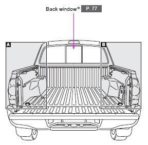
 Luggage compartment
*: If equipped ...
Other materials:
Parking brake
Lever type
● Sets the parking brake
Fully set the parking brake while depressing the brake pedal.
At this time, the indicator will come on.
● Release the parking brake
Press the button
Turn the lever clockwise
Press it in completely
Pedal type
Sets the parking brake*.
...
Using the radio
Select ŌĆ£AMŌĆØ or ŌĆ£FMŌĆØ on the ŌĆ£Select Audio SourceŌĆØ screen to begin listening
to the radio.
Audio control screen
ŌĆ£Select Audio SourceŌĆØ screen
appears
Preset stations
Select to display RBDS text
message
Scanning for receivable station
Sele ...
Tonneau Cover Assembly
Removal
REMOVAL
PROCEDURE
1. REMOVE TOP COVER SUB-ASSEMBLY
(a) Open the cover.
(b) Remove the bolt and top cover sub-assembly.
2. REMOVE REAR BODY SIDE PANEL PROTECTOR
Click here
Installation
INSTALLATION
PROCEDURE
1. INSTALL REAR ...
