Toyota Tacoma (2015-2018) Service Manual: Open Circuit in IG1/IG2 Power Source Circuit (C1242)
DESCRIPTION
If there is a problem with the skid control ECU (master cylinder solenoid) power supply circuit, the skid control ECU outputs the DTC and prohibits operation under the fail safe function.
If the voltage supplied to terminal IG1 and/or IG2 is not within the DTC detection threshold due to malfunctions in parts such as the battery or alternator circuit, this DTC is stored.
|
DTC No. |
DTC Detecting Condition |
Trouble Areas |
|---|---|---|
|
C1242 |
Vehicle speed 3 km/h (1.9 mph) or more and voltage of skid control ECU (master cylinder solenoid) terminal IG1 and/or IG2 remains at below 6.5 V for more than 7 seconds. |
|
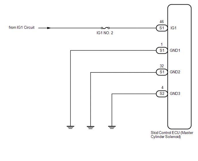
WIRING DIAGRAM
CAUTION / NOTICE / HINT
NOTICE:
- When replacing the skid control ECU (master cylinder solenoid), perform
zero point calibration (See page
.gif) ).
). - Inspect the fuses for circuits related to this system before performing the following inspection procedure.
PROCEDURE
|
1. |
INSPECT BATTERY |
(a) Check the battery voltage.
Standard Voltage:
11 to 14 V
| NG | .gif) |
GO TO CHARGING SYSTEM |
|
.gif)
|
2. |
CHECK HARNESS AND CONNECTOR (IG2 TERMINAL) |
|
(a) Disconnect the skid control ECU (master cylinder solenoid) connector. |
|
(b) Turn the ignition switch to the ON position.
(c) Measure the voltage.
Standard Voltage:
|
Tester Connection |
Specified Condition |
|---|---|
|
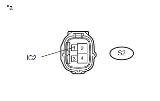
S2-1 (IG2) - Body ground |
10 to 14 V |
|
*a |
Front view of wire harness connector (to Skid Control ECU (Master Cylinder Solenoid)) |
(d) Reconnect the skid control ECU (master cylinder solenoid) connector.
(e) Turn the ignition switch to OFF.
| NG | |
REPAIR OR REPLACE HARNESS OR CONNECTOR |
|
|
3. |
CHECK HARNESS AND CONNECTOR (GND TERMINAL) |
|
(a) Disconnect the skid control ECU (master cylinder solenoid) connectors. |
|
(b) Measure the resistance.
Standard Resistance:
|
Tester Connection |
Specified Condition |
|---|---|
|
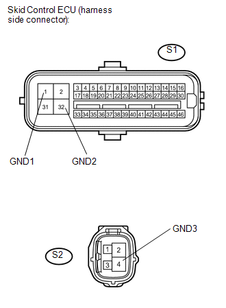
S1-1 (GND1) - Body ground |
Below 1 Ω |
|
S1-32 (GND2) - Body ground |
Below 1 Ω |
|
S2-4 (GND3) - Body ground |
Below 1 Ω |
(c) Reconnect the skid control ECU (master cylinder solenoid) connectors.
| NG | |
REPAIR OR REPLACE HARNESS OR CONNECTOR |
|
|
4. |
RECONFIRM DTC |
(a) Clear the DTCs (See page
).
(b) Drive the vehicle at a speed of 3 km/h (1.9 mph) or more for 7 seconds or more.
(c) Check if the same DTCs are detected.
|
Result |
Proceed to |
|---|---|
|
DTC output |
A |
|
DTC not output |
B |
| A | |
REPLACE MASTER CYLINDER SOLENOID |
| B | |
END |
 Low Power Supply Voltage Malfunction (C1241)
DESCRIPTION
If there is a problem with the skid control ECU (master cylinder solenoid) power
supply circuit, the skid control ECU outputs the DTC and prohibits operation under
the fail-safe funct ...
 Open in Pump Motor Circuit (C1251)
DESCRIPTION
The motor relay (semiconductor relay) is built into the master cylinder solenoid
and drives the pump motor based on a signal from the skid control ECU (master cylinder
solenoid).
...
Other materials:
Entire Combination Meter does not Operate
DESCRIPTION
This circuit is the power source circuit for the meter. This circuit provides
two types of power sources, one is a constant power source mainly used as a backup
power source, and the other is an IG power source mainly used for signal transmission.
The constant power source is main ...
Removal
REMOVAL
CAUTION / NOTICE / HINT
CAUTION:
Some of these service operations affect the SRS airbag system. Read the precautionary
notices concerning the SRS airbag system before servicing (See page
).
HINT:
Use the same procedure for both the RH and LH sides.
The procedure describe ...
Pressure Control Solenoid "G" Circuit Open (P280713)
DESCRIPTION
Changing from 1st to 6th is performed by the ECM turning shift solenoid valves
SL1, SL2, SL3 and SL4 on and off. If an open or short circuit occurs in any of the
shift solenoid valves, the ECM controls the remaining normal shift solenoid valves
to allow the vehicle to be operated ...
