Toyota Tacoma (2015-2018) Service Manual: Installation
INSTALLATION
PROCEDURE
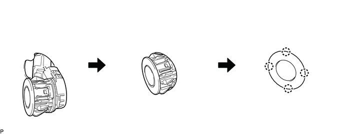
1. INSTALL NO. 1 ULTRASONIC SENSOR
HINT:
Use the same procedure for both sides.
(a) Engage the 4 claws to install the 4 No. 1 ultrasonic sensors as shown in the illustration.
2. INSTALL REAR BUMPER EXTENSION LH (w/ Towing Package)
(See page .gif) )
)
3. INSTALL REAR BUMPER EXTENSION LH (w/o Towing Package)
(See page )
4. INSTALL REAR BUMPER EXTENSION RH (w/ Towing Package)
HINT:
Use the same procedure as for the LH side.
5. INSTALL REAR BUMPER EXTENSION RH (w/o Towing Package)
HINT:
Use the same procedure as for the LH side.
6. INSTALL REAR BUMPER PAD SUB-ASSEMBLY (w/ Towing Package)
(See page )
7. INSTALL REAR BUMPER PAD SUB-ASSEMBLY (w/o Towing Package)
(See page )
8. INSTALL CONNECTOR COVER (w/ Towing Package)
(See page )
9. INSTALL REAR BUMPER HOLE COVER (w/o Towing Package)
(See page )
10. INSTALL REAR BUMPER ASSEMBLY (w/ Towing Package)
(See page )
11. INSTALL REAR BUMPER ASSEMBLY (w/o Towing Package)
(See page )
 Removal
REMOVAL
PROCEDURE
1. REMOVE REAR BUMPER ASSEMBLY (w/ Towing Package)
(See page )
2. REMOVE REAR BUMPER ASSEMBLY (w/o Towing Package)
(See page )
3. REMOVE CONNECTOR COVER (w/ Towing Package) ...
 Brake
Brake
...
Other materials:
Front Crankshaft Oil Seal
Components
COMPONENTS
ILLUSTRATION
Installation
INSTALLATION
PROCEDURE
1. INSTALL TIMING GEAR CASE OR TIMING CHAIN CASE OIL SEAL
(a) Apply MP grease to the lip of a new timing gear case or timing chain case
oil seal.
(b) Using SST and a hammer, tap in the timing gear case ...
Stereo Component Amplifier Malfunction (B15A3)
DESCRIPTION
This DTC is stored when a malfunction occurs in the stereo component amplifier
assembly.
DTC No.
DTC Detection Condition
Trouble Area
B15A3
When one of the conditions below is met:
Internal power supply malfun ...
Low Beam Headlight Circuit
DESCRIPTION
The main body ECU (multiplex network body ECU) controls the low beam headlights.
WIRING DIAGRAM
CAUTION / NOTICE / HINT
NOTICE:
Inspect the fuses for circuits related to this system before performing
the following inspection procedure.
If the main body ECU (multipl ...
