Toyota Tacoma (2015-2018) Service Manual: Components
COMPONENTS
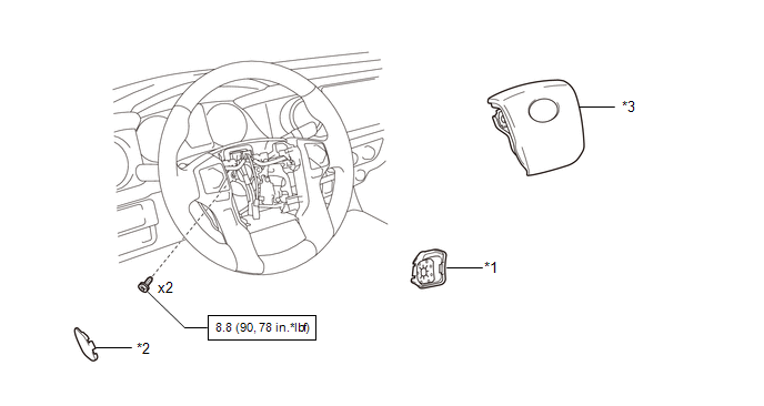
ILLUSTRATION
|
*1 |
LOWER NO. 2 STEERING WHEEL COVER |
*2 |
LOWER NO. 3 STEERING WHEEL COVER |
|
*3 |
STEERING PAD |
- |
- |
.png) |
N*m (kgf*cm, ft.*lbf): Specified torque |
- |
- |
 Steering Pad
...
 On-vehicle Inspection
ON-VEHICLE INSPECTION
PROCEDURE
1. INSPECT STEERING PAD (for Vehicle not Involved in Collision)
(a) Perform a diagnostic system check (See page
).
(b) With the steering pad installed on the vehi ...
Other materials:
Data List / Active Test
DATA LIST / ACTIVE TEST
1. DATA LIST
HINT:
Using the Techstream to read the Data List allows the values or states of switches,
sensors, actuators and other items to be read without removing any parts. This non-intrusive
inspection can be very useful because intermittent conditions or signals ...
Operation Check
OPERATION CHECK
1. CHECK SMART KEY SYSTEM (for Entry Function) OPERATION
NOTICE:
Make sure that the smart key system (for Entry Function) has not been canceled
before performing this inspection.
(a) Check the entry unlock function (driver door).
(1) Perform a wireless lock operation to lock t ...
How To Proceed With Troubleshooting
PROCEDURE
1.
CHECK TIRE AND WHEEL SYSTEM
DIAGNOSIS OF IRREGULAR TIRE WEAR
GO TO STEP 11
DIAGNOSIS OF TIRE VIBRATION
2.
TIGHTEN WHEEL NUTS
...
