Toyota Tacoma (2015-2018) Service Manual: Installation
INSTALLATION
PROCEDURE
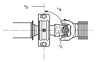
1. INSPECT PROPELLER SHAFT WITH CENTER BEARING ASSEMBLY (with Grease Fitting)
 Text in Illustration
|
*1 |
Grease Fitting |
- |
- |
|
*a |
View A |
*b |
Front Side |
HINT:
When replacing the spider bearing, make sure that the grease fitting assembly hole is facing in the direction shown in the illustration.
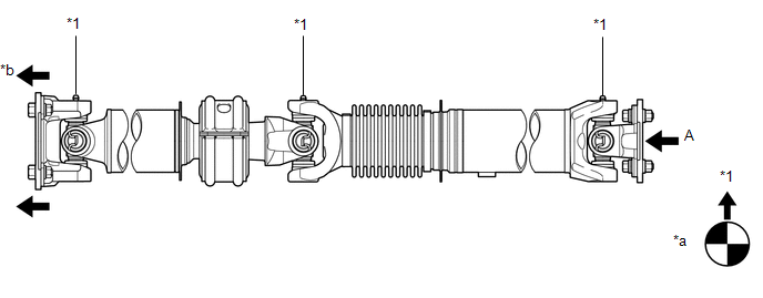
2. INSTALL PROPELLER SHAFT WITH CENTER BEARING ASSEMBLY
|
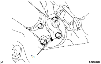
(a) Align the matchmarks on the propeller shaft flange yoke and transfer flange. Text in Illustration
|
|
(b) Install the propeller shaft with the 4 nuts and 4 washers.
Torque:
88 N·m {899 kgf·cm, 65 ft·lbf}
|
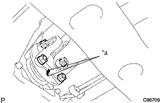
(c) Align the matchmarks on the propeller shaft flange yoke and differential flange. Text in Illustration
|
|
(d) for Differential Type BD20:
(1) Install the propeller shaft with the 4 bolts, 4 washers and 4 nuts.
Torque:
88 N·m {899 kgf·cm, 65 ft·lbf}
(e) for Differential Type BD22:
(1) Install the propeller shaft with the 4 washers and 4 nuts.
Torque:
88 N·m {899 kgf·cm, 65 ft·lbf}
|
(f) Provisionally install the center support bearing with 2 mounting bolts. Text in Illustration
HINT: Make sure the bearing is installed with the drain hole facing downwards. |
|
(g) Tighten the 2 bolts.
Torque:
36 N·m {369 kgf·cm, 27 ft·lbf}
 Inspection
INSPECTION
PROCEDURE
1. INSPECT PROPELLER SHAFT WITH CENTER BEARING ASSEMBLY
(a) Using a dial indicator, check the propeller shaft runout.
Maximum runout:
0.6 mm (0.0236 in.)
If the shaft run ...
 Reassembly
REASSEMBLY
PROCEDURE
1. INSPECT CENTER NO. 2 SUPPORT BEARING ASSEMBLY
(a) Turn the center bearing by hand, check that it turns smoothly without catching
and that there are no cracks or damage.
...
Other materials:
System Diagram
SYSTEM DIAGRAM
Communication Table
Transmitting ECU
Receiving ECU
Signal
Communication Method
Power Window Regulator Master Switch Assembly
Power Window Regulator Motor Assembly (for Driver Door)
Power Window ...
Front Radar Sensor (C1A10)
DESCRIPTION
When an internal malfunction is detected in the millimeter wave radar sensor
assembly, DTC C1A10 is stored.
DTC No.
Detection Item
DTC Detection Condition
Trouble Area
C1A10
Front Radar Sensor
When the ...
4WD Control Switch Circuit
WIRING DIAGRAM
PROCEDURE
1.
CONFIRM PROBLEM SYMPTOM
(a) Confirm the problem symptoms.
Result
Result
Proceed to
The 4WD indicator light (green) and 4LO indicator light remain off
A
The 4WD indica ...
