Toyota Tacoma (2015-2018) Service Manual: Installation
INSTALLATION
PROCEDURE
1. INSTALL TRANSMISSION CASE GASKET
(a) Install 2 new transmission case gaskets to the automatic transmission case sub-assembly.
2. INSTALL MANUAL VALVE
(a) Coat the manual valve with ATF and install it to the transmission valve body assembly.
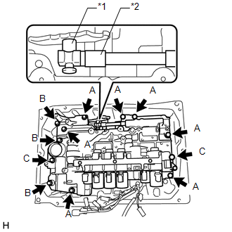
3. INSTALL TRANSMISSION VALVE BODY ASSEMBLY
|
(a) Insert the manual valve lever sub-assembly into the groove on the end of the manual valve and install the transmission valve body assembly to the automatic transmission case sub-assembly with the 12 bolts. Text in Illustration
Torque: 11 N·m {112 kgf·cm, 8 ft·lbf} HINT: Bolt length:
|
|
(b) Install the detent spring and detent spring cover to the transmission valve body assembly with the bolt.
Torque:
10 N·m {102 kgf·cm, 7 ft·lbf}
4. INSTALL VALVE BODY OIL STRAINER ASSEMBLY
(a) Coat a new O-ring with ATF, and install it to the valve body oil strainer assembly.
(b) Install the valve body oil strainer assembly to the transmission valve body assembly with the 3 bolts.
Torque:
10 N·m {102 kgf·cm, 7 ft·lbf}
5. CONNECT TRANSMISSION WIRE
(See page .gif) )
)
6. CHECK AUTOMATIC TRANSMISSION SYSTEM
(See page )
 Reassembly
REASSEMBLY
PROCEDURE
1. INSTALL SHIFT SOLENOID VALVE SLT
(a) Install the shift solenoid valve SLT and straight pin to the transmission
valve body assembly.
...
 Axle
Axle
...
Other materials:
Diagnosis System
DIAGNOSIS SYSTEM
1. DESCRIPTION
(a) The steering lock ECU (steering lock actuator or UPR bracket assembly) stores
DTCs when a malfunction occurs in the system. These DTCs can be confirmed by using
the Techstream.
NOTICE:
When using the Techstream with the engine switch off to confirm ...
Problem Symptoms Table
PROBLEM SYMPTOMS TABLE
If a normal code is displayed during the DTC check but the problem still occurs,
check the circuits for each problem symptom in the order given in the table below
and proceed to the relevant troubleshooting page.
NOTICE:
When replacing the skid control ECU (master cylin ...
Purge Valve
Components
COMPONENTS
ILLUSTRATION
Inspection
INSPECTION
PROCEDURE
1. INSPECT PURGE VSV
(a) Measure the resistance according to the value(s) in the table below.
Text in Illustration
*a
Component without harness connected
(Purge VSV ...
