Toyota Tacoma (2015-2018) Service Manual: Installation
INSTALLATION
PROCEDURE
1. INSTALL TRANSMISSION WIRE
(a) Coat 2 new O-rings with ATF, and install them to the 2 temperature sensors.
(b) Coat a new O-ring with ATF, and install it to the transmission wire.
(c) Install the transmission wire to the automatic transmission case sub-assembly with the bolt.
Torque:
5.4 N·m {55 kgf·cm, 48 in·lbf}
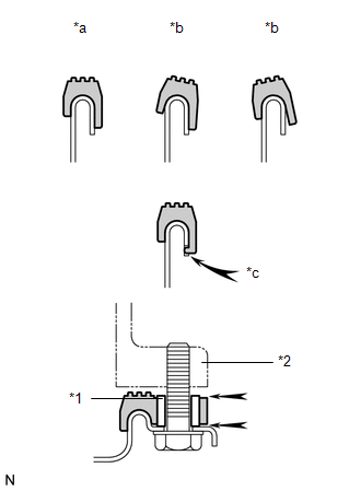
(d) Connect the transmission wire connector.
HINT:
Push up the lever until the claw of the transmission wire connector makes a connection sound.
2. INSTALL TRANSMISSION INSULATOR RH (for 2GR-FKS)
(a) Install the transmission insulator RH to the automatic transmission assembly with the 2 bolts.
Torque:
14 N·m {143 kgf·cm, 10 ft·lbf}
(b) Install the wire harness clamp bracket to the transmission insulator RH with the bolt.
Torque:
13 N·m {127 kgf·cm, 9 ft·lbf}
3. INSTALL TRANSMISSION INSULATOR RH (for 2TR-FE)
(a) Install the transmission insulator RH to the automatic transmission assembly with the 3 bolts.
Torque:
14 N·m {143 kgf·cm, 10 ft·lbf}
4. CONNECT TRANSMISSION WIRE
|
(a) Connect the 7 solenoid valve connectors. Text in Illustration
|
|
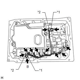
(b) Install the 2 temperature sensors and 2 temperature sensor clamps to the transmission valve body assembly with the bolt.
Torque:
for Bolt A :
10 N·m {102 kgf·cm, 7 ft·lbf}
for Bolt B :
11 N·m {112 kgf·cm, 8 ft·lbf}
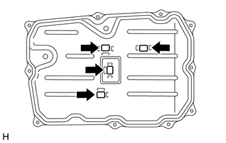
5. INSTALL AUTOMATIC TRANSMISSION OIL PAN SUB-ASSEMBLY
|
(a) Install the 4 transmission oil cleaner magnets to the automatic transmission oil pan sub-assembly as shown in the illustration. |
|
(b) Install a new automatic transmission oil pan gasket to the automatic transmission oil pan sub-assembly.
|
(c) Install the automatic transmission oil pan sub-assembly with automatic transmission oil pan gasket to the automatic transmission case sub-assembly with the 10 bolts. Text in Illustration
Torque: 7.4 N·m {75 kgf·cm, 65 in·lbf} NOTICE:
|
|
6. ADD AUTOMATIC TRANSMISSION FLUID
(See page .gif) )
)
 Removal
REMOVAL
PROCEDURE
1. DRAIN AUTOMATIC TRANSMISSION FLUID
(a) Remove the drain plug and gasket from the automatic transmission
assembly and drain the ATF.
...

Other materials:
Freeze Frame Data
FREEZE FRAME DATA
DESCRIPTION
(a) Whenever a forward recognition camera system DTC is stored, the forward recognition
camera stores the current vehicle state (ECU and sensor information) as Freeze Frame
Data.
CHECK FREEZE FRAME DATA
(a) Connect the Techstream to the DLC3.
(b) Turn the ignit ...
Perchlorate Material
Special handling may apply, See www.dtsc.ca.gov/hazardouswaste/perchlorate.
Your vehicle has components that may contain perchlorate. These components may
include airbag, seat belt pretensioners, and wireless remote control batteries.
CAUTION
■General precautions while driving
Driving un ...
Panel Switches do not Function
PROCEDURE
1.
CHECK PANEL SWITCH
(a) Check for foreign matter around the switches that might prevent operation.
OK:
No foreign matter is found.
NG
REMOVE ANY FOREIGN MATTER FOUND
OK
...
