Toyota Tacoma (2015-2018) Service Manual: Inspection
INSPECTION
PROCEDURE
1. INSPECT GENERATOR BRUSH HOLDER ASSEMBLY
|
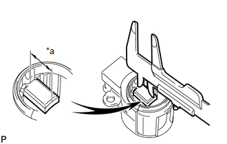
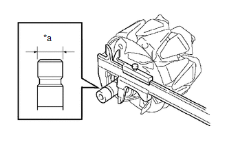
(a) Using a vernier caliper, measure the brush length. Text in Illustration
Standard exposed length: 9.5 to 11.5 mm (0.374 to 0.453 in.) Minimum exposed length: 4.5 mm (0.177 in.) If the brush length is less than the minimum, replace the generator brush holder assembly. |
|
2. INSPECT GENERATOR ROTOR ASSEMBLY
|
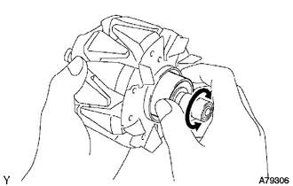
(a) Check that the generator rotor bearing is not rough or worn. If necessary, replace the generator rotor assembly. |
|
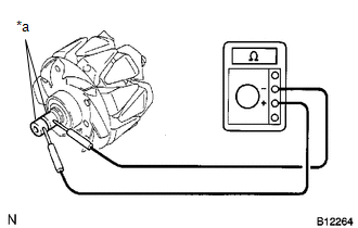
(b) Check the generator rotor assembly for an open circuit.
|
(1) Measure the resistance according to the value(s) in the table below. Text in Illustration
Standard Resistance:
If the result is not as specified, replace the generator rotor assembly. |
|
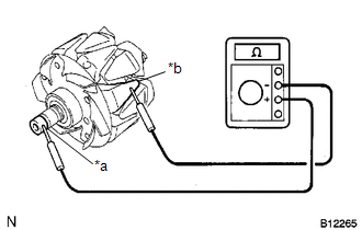
(c) Check the generator rotor assembly for an open circuit.
|
(1) Measure the resistance according to the value(s) in the table below. Text in Illustration
Standard Resistance:
If the result is not as specified, replace the generator rotor assembly. |
|
|
(d) Using a vernier caliper, measure the slip ring diameter. Text in Illustration
Standard diameter: 14.2 to 14.8 mm (0.559 to 0.583 in.) Minimum diameter: 14.0 mm (0.551 in.) If the diameter is less than the minimum, replace the generator rotor assembly. |
|
 Disassembly
DISASSEMBLY
PROCEDURE
1. REMOVE GENERATOR PULLEY
(a) Mount the generator assembly in the vise between aluminum plates.
NOTICE:
Do not overtighten the vise.
(b) Install SST 1-A to the generator p ...
 Installation
INSTALLATION
PROCEDURE
1. INSTALL GENERATOR ASSEMBLY
(a) Install the generator bracket to the generator assembly with the bolt.
Torque:
20 N·m {204 kgf·cm, 15 ft·lbf}
(b) Install the generat ...
Other materials:
IG Signal Circuit
DESCRIPTION
This circuit detects whether the ignition switch is ON or off, and sends this
information to the main body ECU (multiplex network body ECU).
WIRING DIAGRAM
CAUTION / NOTICE / HINT
NOTICE:
Inspect the fuses for circuits related to this system before performing
the fol ...
Steering Angle Sensor Zero Point Malfunction (C1290)
DESCRIPTION
The skid control ECU (master cylinder solenoid) acquires steering angle sensor
zero point every time the ignition switch is turned to ON and the vehicle is driven
at 35 km/h (22 mph) or more for approximately 5 seconds. The ECU also stores the
previous zero point.
If the front wh ...
Fuel Sender Gauge Assembly
Components
COMPONENTS
ILLUSTRATION
Inspection
INSPECTION
PROCEDURE
1. INSPECT FUEL SENDER GAUGE ASSEMBLY
(a) Check that the float moves smoothly between F and E.
Text in Illustration
*a
Component without harness connected
(Fuel Sen ...
