Toyota Tacoma (2015-2018) Service Manual: Inspection
INSPECTION
PROCEDURE
1. INSPECT FRONT NO. 1 SPEAKER ASSEMBLY (w/o Amplifier Box Speaker Assembly)
(a) Measure the resistance according to the value(s) in the table below.
Standard resistance:
|
Tester Connection |
Condition |
Specified Condition |
|---|---|---|
|
1 - 2 |
Always |
3.2 to 4.8 Ω |
If the result is not as specified, replace the front No. 1 speaker assembly.
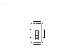
Text in Illustration|
*a |
Component without harness connected (Front No. 1 Speaker Assembly) |
2. INSPECT FRONT NO. 1 SPEAKER ASSEMBLY (w/ Amplifier Box Speaker Assembly)
(a) Measure the resistance according to the value(s) in the table below.
Standard resistance:
|
Tester Connection |
Condition |
Specified Condition |
|---|---|---|
|
1 - 2 |
Always |
1.4 to 2.2 Ω |
If the result is not as specified, replace the front No. 1 speaker assembly.
Text in Illustration|
*a |
Component without harness connected (Front No. 1 Speaker Assembly) |
 Removal
REMOVAL
CAUTION / NOTICE / HINT
HINT:
Use the same procedure for the RH and LH sides.
The procedure listed below is for the LH side.
PROCEDURE
1. REMOVE FRONT DOOR LOWER FRAME B ...
 Installation
INSTALLATION
CAUTION / NOTICE / HINT
HINT:
Use the same procedure for the RH and LH sides.
The procedure listed below is for the LH side.
PROCEDURE
1. INSTALL FRONT NO. 1 SPEAKE ...
Other materials:
Removal
REMOVAL
PROCEDURE
1. REMOVE FRONT WHEEL
2. INSPECT FRONT SUSPENSION LOWER ARM
(a) Install the hub nuts onto the disc.
(b) Using a dial indicator, check the lower ball joint for excessive play when
you push the hub nuts up and down with a force of 294 N (30 kgf, 66 lbf).
Maximum:
0.5 mm ( ...
Installation
INSTALLATION
CAUTION / NOTICE / HINT
PROCEDURE
1. INSTALL REAR AIRBAG SENSOR LH
(a) Check that the ignition switch is OFF.
(b) Check that the cable is disconnected from the battery negative (-) terminal.
CAUTION:
After disconnecting the cable from the terminal, wait for at least 90 seconds
...
Open or Short in Front Speed Sensor RH Circuit (C1405,C1406)
DESCRIPTION
Refer to DTCs C1401 and C1402 (See page ).
DTC Code
DTC Detection Condition
Trouble Area
C1405
C1406
Either condition is met:
An open in the speed sensor signal circuit continues for 0.5
seconds or mor ...
