Toyota Tacoma (2015-2018) Service Manual: Parts Location
PARTS LOCATION
ILLUSTRATION
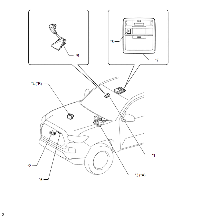
|
*A |
for Hydraulic Brake Booster |
*B |
for Vacuum Brake Booster |
|
*1 |
FORWARD RECOGNITION CAMERA |
*2 |
MILLIMETER WAVE RADAR SENSOR ASSEMBLY |
|
*3 |
HYDRAULIC BRAKE BOOSTER - SKID CONTROL ECU |
*4 |
BRAKE ACTUATOR ASSEMBLY - SKID CONTROL ECU |
|
*5 |
FORWARD RECOGNITION HOOD |
*6 |
MILLIMETER WAVE RADAR WIRE |
|
*7 |
ROOF CONSOLE BOX ASSEMBLY |
*8 |
VSC OFF SWITCH |
ILLUSTRATION
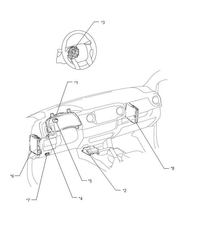
|
*1 |
COMBINATION METER ASSEMBLY - PCS WARNING LIGHT |
*2 |
AIRBAG SENSOR ASSEMBLY - YAW RATE SENSOR |
|
*3 |
STEERING ANGLE SENSOR (SPIRAL CABLE WITH SENSOR SUB-ASSEMBLY) |
*4 |
STOP LIGHT SWITCH ASSEMBLY |
|
*5 |
SKID CONTROL BUZZER |
*6 |
DRIVER SIDE JUNCTION BLOCK - ECU-IG NO. 2 - IG1 NO. 2 |
|
*7 |
DLC3 |
*8 |
ECM |
 Precaution
PRECAUTION
PRECAUTION FOR DISCONNECTING CABLE FROM NEGATIVE BATTERY TERMINAL
NOTICE:
When disconnecting the cable from the negative (-) battery terminal,
initialize the following system ...
 System Description
SYSTEM DESCRIPTION
PRE-COLLISION SYSTEM DESCRIPTION
(a) The pre-collision system uses the pre-collision warning control, pre-collision
brake assist control and pre-collision braking control to hel ...
Other materials:
Removal
REMOVAL
CAUTION / NOTICE / HINT
HINT:
Use the same procedure for both the RH and LH sides.
The procedure described below is for the LH side.
PROCEDURE
1. PRECAUTION
CAUTION:
Be sure to read Precaution thoroughly before servicing (See page
).
NOTICE:
After turning the ign ...
On-vehicle Inspection
ON-VEHICLE INSPECTION
PROCEDURE
1. INSPECT FUEL CUT OPERATION
(a) Start the engine and warm it up.
(b) Increase the engine speed to at least 3500 rpm.
(c) Use a sound scope to check for fuel injector assembly operation noise.
(d) Check that when the accelerator pedal is released, fuel injector ...
Problem Symptoms Table
PROBLEM SYMPTOMS TABLE
HINT:
Use the table below to help determine the cause of problem symptoms. If multiple
suspected areas are listed, the potential causes of the symptoms are listed in order
of probability in the "Suspected Area" column of the table. Check each symptom by
check ...
