Toyota Tacoma (2015-2018) Service Manual: Inspection
INSPECTION
PROCEDURE
1. INSPECT AUTO HIGH BEAM SWITCH
|
*a |
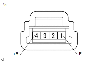
Component without harness connected (Auto High Beam Switch) |
(a) Check the resistance.
(1) Measure the resistance according to the value(s) in the table below.
Standard Resistance:
|
Tester Connection |
Switch Condition |
Specified Condition |
|---|---|---|
| If the result is not as specified, replace the auto high beam switch. | ||
|
4 (+B) - 1 (E) |
Auto high beam switch ON |
Below 1 Ω |
|
Auto high beam switch OFF |
10 kΩ or higher |
|
|
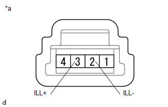
(b) Check the illumination. (1) Apply battery voltage to the connector and check the illumination condition. OK:
|
|
||||||||||
 Components
COMPONENTS
ILLUSTRATION
*A
for Double Cab
*B
for Access Cab
*1
AUTO HIGH BEAM SWITCH
*2
COWL SIDE TRIM ...
 Removal
REMOVAL
PROCEDURE
1. REMOVE FRONT DOOR SCUFF PLATE LH
for Double Cab:
Click here
for Access Cab:
Click here
2. REMOVE COWL SIDE TRIM BOARD LH
Click here
3. REMOVE INSTRUMENT CLUSTER CEN ...
Other materials:
Disassembly
DISASSEMBLY
PROCEDURE
1. REMOVE STARTER YOKE ASSEMBLY
(a) Remove the nut and disconnect the lead wire from terminal C.
(b) Remove the 2 bolts.
(c) Pull out the starter yoke assembly and commutator end frame together with
the starter armatur ...
Output Speed Sensor Circuit No Signal (P0722,P077C,P077D)
DESCRIPTION
This sensor detects the rotation speed of the transmission output shaft and sends
signals to the ECM. By comparing the input turbine speed signal (NT) with the output
shaft speed sensor signal (SP2), the ECM detects the shift timing of the gears and
appropriately controls the engi ...
How To Proceed With Troubleshooting
CAUTION / NOTICE / HINT
HINT:
Use the following procedure listed to troubleshoot the touch select
2-4 and high-low system.
*: Use the Techstream.
PROCEDURE
1.
VEHICLE BROUGHT TO WORKSHOP
NEXT
...
