Toyota Tacoma (2015-2018) Service Manual: Components
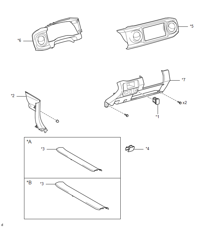
COMPONENTS
ILLUSTRATION
|
*A |
for Double Cab |
*B |
for Access Cab |
|
*1 |
AUTO HIGH BEAM SWITCH |
*2 |
COWL SIDE TRIM BOARD LH |
|
*3 |
FRONT DOOR SCUFF PLATE LH |
*4 |
HOOD LOCK CONTROL LEVER SUB-ASSEMBLY |
|
*5 |
INSTRUMENT CLUSTER CENTER FINISH PANEL SUB-ASSEMBLY |
*6 |
INSTRUMENT CLUSTER FINISH PANEL ASSEMBLY |
|
*7 |
INSTRUMENT PANEL LOWER FINISH PANEL SUB-ASSEMBLY |
- |
- |

 Inspection
INSPECTION
PROCEDURE
1. INSPECT AUTO HIGH BEAM SWITCH
*a
Component without harness connected
(Auto High Beam Switch)
(a) Check the resistance.
(1) Measure the ...
Other materials:
Disassembly
DISASSEMBLY
PROCEDURE
1. FIX VANE PUMP ASSEMBLY
(a) Using SST, fix the vane pump assembly in a vise.
SST: 09630-00014
09631-00132
NOTICE:
When using a vise, do not overtighten it.
2. REMOVE POWER STEERING SUCTION PORT UNION
...
Data List / Active Test
DATA LIST / ACTIVE TEST
1. DATA LIST
NOTICE:
In the table below, the values listed under "Normal Condition" are reference
values. Do not depend solely on these reference values when deciding whether a part
is faulty or not.
HINT:
Using the Techstream to read the Data List allows t ...
A/C ECU Vehicle Information Reading/Writing Processor Malfunction (B15F5)
DESCRIPTION
This DTC is stored when items controlled by the air conditioning amplifier assembly
cannot be customized via the audio and visual system vehicle customization screen.
HINT:
The air conditioning amplifier assembly controls the air conditioning system
related items that are customiz ...
