Toyota Tacoma (2015-2018) Service Manual: Inspection
INSPECTION
PROCEDURE
1. INSPECT SHIFT SOLENOID VALVE SL1
|
(a) Measure the resistance according to the value(s) in the table below. Text in Illustration
Standard Resistance:
If the value is not as specified, replace the shift solenoid valve SL1. |
|
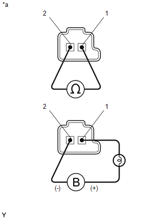
(b) Apply 12 V battery voltage to the shift solenoid valve and check that the valve moves and makes an operating noise.
OK:
|
Measurement Condition |
Specified Condition |
|---|---|
|
Valve moves and makes an operating noise |
If the operation cannot be done as specified, replace the shift solenoid valve SLT.
2. INSPECT SHIFT SOLENOID VALVE SL2
HINT:
Refer to Inspect Shift Solenoid Valve SL1.
3. INSPECT SHIFT SOLENOID VALVE SL3
HINT:
Refer to Inspect Shift Solenoid Valve SL1.
4. INSPECT SHIFT SOLENOID VALVE SL4
HINT:
Refer to Inspect Shift Solenoid Valve SL1.
5. INSPECT SHIFT SOLENOID VALVE SLU
HINT:
Refer to Inspect Shift Solenoid Valve SL1.
6. INSPECT SHIFT SOLENOID VALVE SLT
HINT:
Refer to Inspect Shift Solenoid Valve SL1.
7. INSPECT SHIFT SOLENOID VALVE SL
|
(a) Measure the resistance according to the value(s) in the table below. Text in Illustration
Standard Resistance:
If the value is not as specified, replace the shift solenoid valve SL. |
|
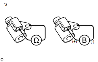
(b) Apply 12 V battery voltage to the shift solenoid valve and check that the valve moves and makes an operating noise.
OK:
|
Measurement Condition |
Specified Condition |
|---|---|
|
Valve moves and makes an operating noise |
 Removal
REMOVAL
PROCEDURE
1. DISCONNECT TRANSMISSION WIRE
(See page )
2. REMOVE VALVE BODY OIL STRAINER ASSEMBLY
(a) Remove the 3 bolts and valve body oil strainer assembly from the
trans ...
 Reassembly
REASSEMBLY
PROCEDURE
1. INSTALL SHIFT SOLENOID VALVE SLT
(a) Install the shift solenoid valve SLT and straight pin to the transmission
valve body assembly.
...
Other materials:
Blind Spot Monitor Master Module Beam Axis Inspection Incomplete (C1ABB)
DESCRIPTION
This DTC is stored when a beam axis inspection has not been performed for the
blind spot monitor sensor LH.
HINT:
This DTC is always stored after replacing a blind spot monitor sensor. The purpose
of this DTC is to ensure that beam axis inspection is performed. Completing the
be ...
Freeze Frame Data
FREEZE FRAME DATA
1. FREEZE FRAME DATA
(a) Using the Techstream, check the vehicle condition (ECU, sensor) when the
brake system operates or a DTC is output.
2. CHECK FREEZE FRAME DATA WHEN BRAKE SYSTEM OPERATES
(a) Freeze frame data is stored when the brake system operates. The freeze frame
...
Installation
INSTALLATION
PROCEDURE
1. INSTALL REAR BUMPER ASSEMBLY
(a) Using an engine lifter or equivalent, engage the 2 pins to install the rear
bumper assembly as shown in the illustration.
Text in Illustration
*a
Pin
-
-
NOTICE:
Using pl ...
