Toyota Tacoma (2015-2018) Service Manual: Ignition Switch
Components
COMPONENTS
ILLUSTRATION
Removal
REMOVAL
PROCEDURE
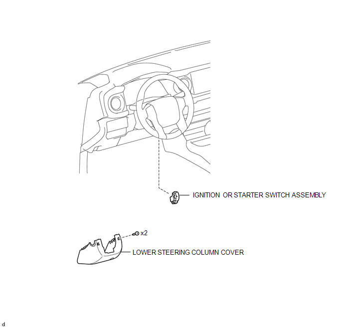
1. REMOVE LOWER STEERING COLUMN COVER
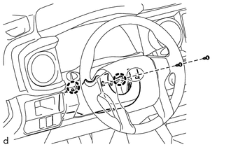
(a) Remove the 2 screws.
(b) Disengage the 2 claws and remove the lower steering column cover.
2. REMOVE IGNITION OR STARTER SWITCH ASSEMBLY
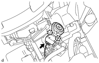
(a) Disconnect the connector.
(b) Disengage the 2 claws and remove the ignition or starter switch assembly.
Inspection
INSPECTION
PROCEDURE
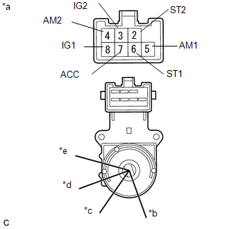
1. INSPECT IGNITION OR STARTER SWITCH ASSEMBLY
|
(a) Check the resistance. Text in Illustration
(1) Measure the resistance according to the value(s) in the table below. Standard Resistance:
If the result is not as specified, replace the ignition or starter switch assembly. |
|
Installation
INSTALLATION
PROCEDURE
1. INSTALL IGNITION OR STARTER SWITCH ASSEMBLY
(a) Engage the 2 claws and install the ignition or starter switch assembly.
(b) Connect the connector.
2. INSTALL LOWER STEERING COLUMN COVER
(a) Engage the 2 claws and install the lower steering column cover.
(b) Install the 2 screws.
HINT:
Turn the steering wheel to the right and left as necessary to install the 2 screws.
 Engine Switch
Components
COMPONENTS
ILLUSTRATION
Inspection
INSPECTION
PROCEDURE
1. INSPECT ENGINE SWITCH
(a) Measure the resistance according to the value(s) in the table below.
Text in Illustration ...

Other materials:
Sleep Operation Failure of Occupant Classification ECU (B1796)
DESCRIPTION
During sleep mode, the occupant detection ECU monitors the condition of each
sensor while the ignition switch is off. In this mode, if the occupant detection
ECU detects an internal malfunction, DTC B1796 is set.
DTC No.
DTC Detections Conditions
Tr ...
Removal
REMOVAL
PROCEDURE
1. DRAIN TRANSFER OIL
2. REMOVE FRONT PROPELLER SHAFT ASSEMBLY
3. REMOVE PROPELLER WITH CENTER BEARING SHAFT ASSEMBLY
4. SUPPORT TRANSMISSION ASSEMBLY
5. REMOVE NO. 3 FRAME CROSSMEMBER SUB-ASSEMBLY
6. REMOVE REAR NO. 1 ENGINE MOUNTING INSULATOR
7. SUPPO ...
Brake Switch "A" Signal Compare Failure (P057162)
DESCRIPTION
When the brake pedal is depressed, the stop light switch assembly sends a signal
to the ECM. When the ECM receives this signal, it cancels the dynamic radar cruise
control. The fail-safe function operates to enable normal driving even if there
is a malfunction in the stop light si ...
