Toyota Tacoma (2015-2018) Service Manual: Engine Switch
Components
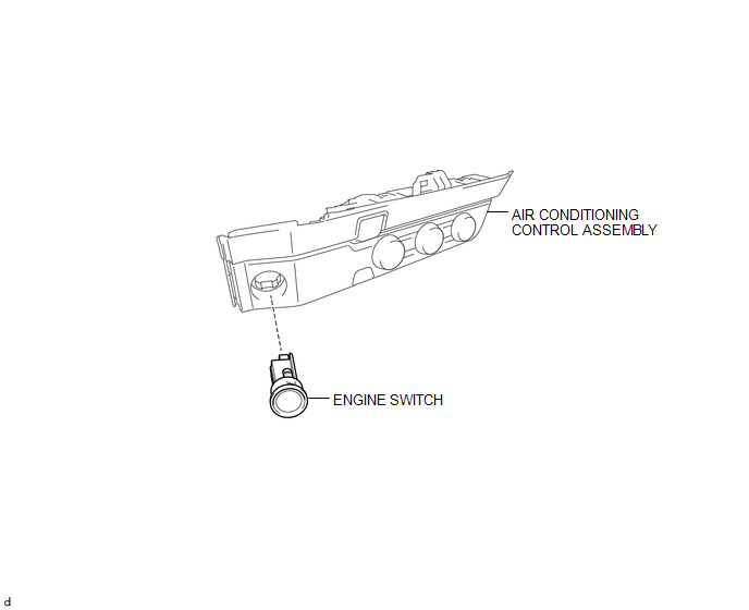
COMPONENTS
ILLUSTRATION
Inspection
INSPECTION
PROCEDURE
1. INSPECT ENGINE SWITCH
(a) Measure the resistance according to the value(s) in the table below.
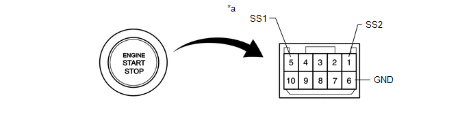 Text in Illustration
|
*a |
Component without harness connected (Engine Switch) |
- |
- |
Standard Resistance:
|
Tester Connection |
Switch Condition |
Specified Condition |
|---|---|---|
|
5 (SS1) - 6 (GND) |
Not pushed |
10 kΩ or higher |
|
1 (SS2) - 6 (GND) |
||
|
5 (SS1) - 6 (GND) |
Pushed |
Below 1 Ω |
|
1 (SS2) - 6 (GND) |
If the result is not as specified, replace the engine switch.
(b) Apply battery voltage between the terminals of the switch, and check the illumination condition of the engine switch.
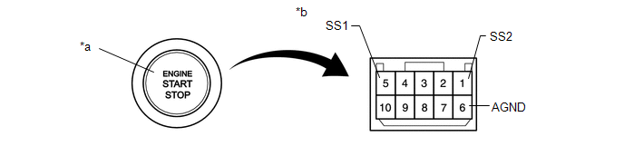 Text in Illustration
|
*a |
Indicator Light |
*b |
Component without harness connected (Engine Switch) |
OK:
|
Measurement Condition |
Specified Condition |
|---|---|
|
Battery positive (+) → Terminal 9 (SWIL) Battery negative (-) → Terminal 6 (GND) |
Illuminates |
HINT:
- If a positive (+) battery lead and a negative (-) battery lead are incorrectly connected, the engine switch indicator light will not illuminate.
- If the voltage is too low, the indicator light will not illuminate.
If the result is not as specified, replace the engine switch.
Installation
INSTALLATION
PROCEDURE
1. INSTALL ENGINE SWITCH
(a) Engage the 2 claws and install the engine switch to the air conditioning control assembly.
2. REMOVE AIR CONDITIONING CONTROL ASSEMBLY
(See page .gif) )
)
Removal
REMOVAL
PROCEDURE
1. REMOVE AIR CONDITIONING CONTROL ASSEMBLY
Seepage .gif)
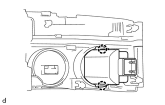
2. REMOVE ENGINE SWITCH
|
(a) Disengage the 2 claws and remove the engine switch from the air conditioning control assembly. |
|
 2gr-fks Starting
...
 Ignition Switch
Components
COMPONENTS
ILLUSTRATION
Removal
REMOVAL
PROCEDURE
1. REMOVE LOWER STEERING COLUMN COVER
(a) Remove the 2 screws.
(b) Disengage the 2 claws and remove the lower steering colu ...
Other materials:
Confirm Cellular Phone Functionality
PROCEDURE
1.
CHECK CUSTOMER'S CELLULAR PHONE COMPATIBILITY
(a) Check if the cellular phone is compatible (Refer to http://www.toyota.com/entune/).
Result
Result
Proceed to
Cellular phone is compatible
A
...
Disassembly
DISASSEMBLY
PROCEDURE
1. INSPECT CONNECTING ROD THRUST CLEARANCE
(a) Using a dial indicator, measure the thrust clearance while moving
the connecting rod back and forth.
Standard thrust clearance:
0.15 to 0.40 mm (0.00591 to 0.0157 in.)
Maximum thrust clearance:
0.50 ...
Pressure Control Solenoid "C" Performance (Shift Solenoid Valve SL3) (P0796)
SYSTEM DESCRIPTION
The ECM uses the vehicle speed signal and signals from the transmission revolution
sensors (NT, SP2) to detect the actual gear (1st, 2nd, 3rd, 4th, 5th or 6th gear).
The ECM compares the actual gear with the shift schedule in the ECM memory to
detect mechanical problems of t ...
