Toyota Tacoma (2015-2018) Service Manual: Front Left Seat Heat Sensor Circuit (B14C1)
DESCRIPTION
Output to the front seat cushion heater assembly LH temperature sensor stops if one of the following occurs: 1) the temperature sensor is open or shorted; or 2) the temperature sensor is damaged and its output value does not change.
|
DTC Code |
DTC Detection Condition |
Trouble Area |
|---|---|---|
|
B14C1 |
Seat heater temperature sensor malfunction |
|
WIRING DIAGRAM
PROCEDURE
|
1. |
CLEAR DTC |
(a) Clear the DTCs (See page .gif) ).
).
|
.gif)
|
2. |
CHECK FOR DTC |
(a) Check for DTCs (See page ).
OK:
DTC B14C1 is not output.
| OK | .gif) |
USE SIMULATION METHOD TO CHECK |
|
|
3. |
READ VALUE USING TECHSTREAM |
(a) Connect the Techstream to the DLC3.
(b) Turn the ignition switch to ON.
(c) Turn the Techstream on.
(d) Enter the following menus: Body Electrical / Air Conditioner / Data List.
(e) Check the value(s) by referring to the table below.
Air Conditioner:
|
Tester Display |
Measurement Item/Range |
Normal Condition |
Diagnostic Note |
|---|---|---|---|
|
FL Seat Heater Temperature |
Front seat LH side seat heater temperature / min: -29.7°C or max: 59.55°C |
Within range from 36 to 42.2°C (96 to 108°F) |
Front seat heater is on |
OK:
The display is as specified in the normal condition column.
Result|
Result |
Proceed to |
|---|---|
|
NG |
A |
|
OK |
B |
| B | |
REPLACE AIR CONDITIONING AMPLIFIER ASSEMBLY |
|
|
4. |
INSPECT FRONT SEAT CUSHION HEATER ASSEMBLY LH |
(a) Remove the front seat cushion heater assembly LH (See page
).
(b) Inspect the front seat cushion heater assembly LH (See page
).
| NG | |
REPLACE FRONT SEAT CUSHION HEATER ASSEMBLY LH |
|
|
5. |
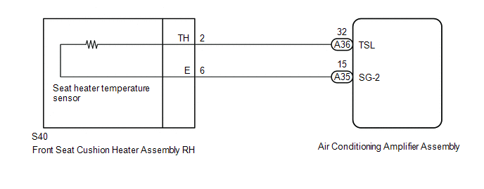
CHECK HARNESS AND CONNECTOR (AIR CONDITIONING AMPLIFIER ASSEMBLY - FRONT SEAT CUSHION HEATER ASSEMBLY LH) |
(a) Disconnect the A35 and A36 air conditioning amplifier assembly connector.
(b) Measure the resistance according to the value(s) in the table below.
Standard Resistance:
|
Tester Connection |
Condition |
Specified Condition |
|---|---|---|
|
A36-32 (TSL) - S40-2 (TH) |
Always |
Below 1 Ω |
|
A35-15 (SG-2) - S40-6 (E) |
Always |
Below 1 Ω |
|
A36-32 (TSL) - Body ground |
Always |
10 kΩ or higher |
|
A35-15 (SG-2) - Body ground |
Always |
10 kΩ or higher |
| OK | |
REPLACE AIR CONDITIONING AMPLIFIER ASSEMBLY |
| NG | |
REPAIR OR REPLACE HARNESS OR CONNECTOR |
 Front Right Seat Heat Sensor Circuit (B14C0)
DESCRIPTION
Output to the front seat cushion heater assembly RH temperature sensor stops
if one of the following occurs: 1) the temperature sensor is open or shorted; or
2) the temperature sensor ...
 Driver Side Seat Heater does not Operate
DESCRIPTION
When the seat heater switch on the air conditioning control assembly is operated,
the air conditioning amplifier assembly receives the signal. The air conditioning
amplifier assembly ...
Other materials:
Sliding Roof Switch Assembly
Components
COMPONENTS
ILLUSTRATION
Installation
INSTALLATION
PROCEDURE
1. INSTALL SLIDING ROOF SWITCH ASSEMBLY (ROOF CONSOLE BOX ASSEMBLY)
(a) Connect the connector.
(b) Engage the 4 clips to install the sliding roof switch assembly (roof console
box assembly).
Removal
REMOVAL
P ...
On-vehicle Inspection
ON-VEHICLE INSPECTION
PROCEDURE
1. INSPECT SPEEDOMETER
(a) Check speedometer operation.
NOTICE:
The meter ECU receives the vehicle speed signal from the skid control
ECU via CAN communication. Therefore, perform the following inspection referring
to values on the Data List of th ...
Pressure Control Solenoid "A" Actuator Stuck Off (P07457F)
SYSTEM DESCRIPTION
The ECM uses the vehicle speed signal and signals from the transmission revolution
sensors (NT, SP2) to detect the actual gear (1st, 2nd, 3rd, 4th, 5th or 6th gear).
The ECM compares the actual gear with the shift schedule in the ECM memory to
detect mechanical problems of t ...
