Toyota Tacoma (2015-2018) Service Manual: ECU Power Source Circuit
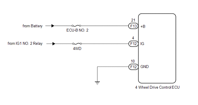
WIRING DIAGRAM
CAUTION / NOTICE / HINT
NOTICE:
Inspect the fuses for circuits related to this system before performing the following inspection procedure.
PROCEDURE
|
1. |
INSPECT BATTERY |
(a) Check the battery voltage.
Standard voltage:
11 to 14 V
| NG | .gif) |
CHECK OR REPLACE CHARGING SYSTEM OR BATTERY |
|
.gif)
|
2. |
CHECK HARNESS AND CONNECTOR (+B AND IG TERMINAL) |
(a) Turn the ignition switch off.
|
(b) Disconnect the 4 wheel drive control ECU connector. |
|
(c) Measure the voltage according to the value(s) in the table below.
Standard Voltage:
|
Tester Connection |
Switch Condition |
Specified Condition |
|---|---|---|
|
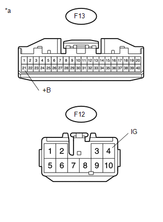
F13-21 (+B) - Body ground |
Always |
11 to 14 V |
|
F12-4 (IG) - Body ground |
Ignition switch ON |
11 to 14 V |
|
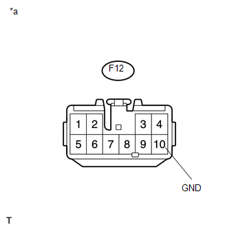
*a |
Front view of wire harness connector (to 4 Wheel Drive Control ECU) |
| NG | |
REPAIR OR REPLACE HARNESS OR CONNECTOR (+B AND IG CIRCUIT) |
|
|
3. |
CHECK HARNESS AND CONNECTOR (GND TERMINAL) |
(a) Turn the ignition switch off.
|
(b) Measure the resistance according to the value(s) in the table below. Standard Resistance:
|
|
| OK | |
PROCEED TO NEXT SUSPECTED AREA SHOWN IN PROBLEM SYMPTOMS TABLE |
| NG | |
REPAIR OR REPLACE HARNESS OR CONNECTOR (GND CIRCUIT) |
 4WD Control Switch Circuit
WIRING DIAGRAM
PROCEDURE
1.
CONFIRM PROBLEM SYMPTOM
(a) Confirm the problem symptoms.
Result
Result
Proceed to
The 4WD ind ...

Other materials:
Transponder Chip Malfunction (B2793,B2794,B2797,B2798)
DESCRIPTION
DTC B2793 is stored when a malfunction is found in the key during key
code registration or a key code is not registered normally. Replace the
key if key code registration cannot be performed normally and this DTC is
output.
DTC B2794 is stored when a key with an i ...
Differential System(w/o Differential Lock)
Precaution
PRECAUTION
1. Before disassembly, clean the outside of the front and rear differential assembly
and remove any sand and mud to prevent it from entering the assembly during disassembly
and installation.
2. When removing connected parts made of a light alloy, such as front and rear ...
Disassembly
DISASSEMBLY
PROCEDURE
1. REMOVE BRAKE ACTUATOR BRACKET NO. 1
(a) Using a hexagon wrench (5 mm), remove the screw and brake actuator bracket
No. 1.
(b) Using a screwdriver, remove the fluid level warning switch connector.
2. REMOVE BRAKE M ...
