Toyota Tacoma (2015-2018) Service Manual: Installation
INSTALLATION
PROCEDURE
1. INSTALL HYDRAULIC BRAKE BOOSTER
(a) Install a new brake booster gasket onto the hydraulic brake booster.
(b) Install the hydraulic brake booster with the 4 nuts.
Torque:
14 N·m {145 kgf·cm, 10 ft·lbf}
|
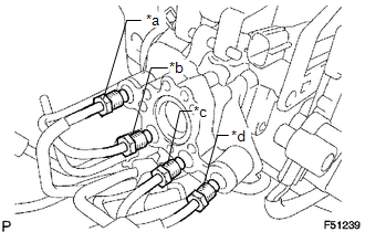
(c) Using a union nut wrench, connect the 4 brake lines to the correct positions of the hydraulic brake booster, as shown in the illustration. Text in Illustration
Torque: without union nut wrench : 15 N·m {155 kgf·cm, 11 ft·lbf} with union nut wrench : 14 N·m {145 kgf·cm, 10 ft·lbf} HINT:
|
|
(d) Connect the 3 connectors.
2. INSTALL MASTER CYLINDER PUSH ROD CLEVIS
.gif)
3. INSTALL LOWER NO. 1 INSTRUMENT PANEL AIRBAG ASSEMBLY
(See page )
4. INSPECT BRAKE PEDAL HEIGHT
5. INSPECT PEDAL FREE PLAY
6. INSPECT PEDAL RESERVE DISTANCE
7. FILL RESERVOIR WITH BRAKE FLUID
8. BLEED BRAKE BOOSTER WITH ACCUMULATOR PUMP ASSEMBLY
9. BLEED BRAKE LINE
10. BLEED MASTER CYLINDER SOLENOID
11. INSPECT FLUID LEVEL IN RESERVOIR
12. INSPECT FOR BRAKE FLUID LEAK
13. INSPECT BRAKE MASTER CYLINDER OPERATION
 Disposal
DISPOSAL
PROCEDURE
1. DISPOSE OF BRAKE BOOSTER ACCUMULATOR ASSEMBLY
(a) Place the brake booster accumulator in a vise and cover it with a cloth.
(b) Slowly cut a hole on the brake booster accumu ...
 Rear Brake
...
Other materials:
Rear Speed Sensor RH Output Malfunction (C1415,C1416)
DESCRIPTION
Refer to DTCs C1403 and C1404 (See page ).
DTC No.
Detection Item
DTC Detection Condition
Trouble Area
C1415
Rear Speed Sensor RH Output Malfunction
Any of the following is detected:
An op ...
Removal
REMOVAL
PROCEDURE
1. REMOVE FRONT FENDER SEAL LH
(a) Remove the 5 clips and front fender seal LH.
2. REMOVE FRONT FENDER SEAL RH
HINT:
Use the same procedure as for the LH side.
3. REMOVE FRONT EXHAUST PIPE ASSEMBLY
(a) Disengag ...
Rear seats (Access Cab and Double Cab models)
Access Cab models
The bottom cushion of the rear seats can be raised and lowered.
■ Before raising the bottom cushion
Stow the seat belt buckles.
This prevents the seat belt buckles from falling out when you fold the seatback.
■ Raising the bottom cushion
Raise the bottom cushi ...
