Toyota Tacoma (2015-2018) Service Manual: Disassembly
DISASSEMBLY
CAUTION / NOTICE / HINT
HINT:
- Use the same procedure for both the LH and RH sides.
- The procedure described below is for the LH side.
PROCEDURE
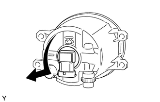
1. REMOVE FOG LIGHT BULB
|
(a) Turn the fog light bulb in the direction indicated by the arrow in the illustration to remove it. NOTICE: Do not touch the fog light bulb glass. |
|
 Components
COMPONENTS
ILLUSTRATION
...
 Removal
REMOVAL
CAUTION / NOTICE / HINT
HINT:
Use the same procedure for both the LH and RH sides.
The procedure described below is for the LH side.
PROCEDURE
1. REMOVE NO. 1 FRONT WHEE ...
Other materials:
Theft Deterrent System Unexpectedly Sets Itself
DESCRIPTION
A situation in which the theft deterrent system unexpectedly sets itself can
be caused when the main body ECU (multiplex network body ECU) cannot detect whether
a door is open or closed.
If the theft deterrent system unexpectedly sets itself, there may be a malfunction
in a court ...
Inspection
INSPECTION
PROCEDURE
1. INSPECT FRONT NO. 2 SPEAKER ASSEMBLY
(a) When there is a malfunction such as noise from a speaker or no sound at all,
replace the speaker with a new one and check that the malfunction disappears.
OK:
Malfunction disappears.
HINT:
Connect the connectors to th ...
Invalid Data Received from Deceleration Sensor (C1442,C1443)
DESCRIPTION
The skid control ECU (master cylinder solenoid) receives signals from the yaw
rate and acceleration sensor (airbag sensor assembly) via the CAN communication
system.
The airbag sensor assembly has a built-in yaw rate and acceleration sensor.
DTC Code
DTC Dete ...
