Toyota Tacoma (2015-2018) Service Manual: Disassembly
DISASSEMBLY
CAUTION / NOTICE / HINT
HINT:
- Use the same procedure for the RH side and LH side.
- The following procedure is for the LH side.
- When removing the No. 2 front wheel opening extension pad or No. 1 front wheel opening extension pad or front wheel opening extension pad, heat the front fender wheel opening moulding using a heat light.
- When removing the No. 3 body outside moulding pad or No. 2 body outside moulding pad or No. 1 body outside moulding pad, heat the quarter panel wheel opening moulding using a heat light.
|
Item |
Temperature |
|---|---|
|
Front Fender Wheel Opening Moulding or Quarter Panel Wheel Opening Moulding |
20 to 30°C (68 to 86°F) |
NOTICE:
Do not heat the front fender wheel opening moulding or quarter panel wheel opening moulding excessively.
PROCEDURE
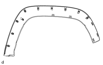
1. REMOVE NO. 2 FRONT WHEEL OPENING EXTENSION PAD
(a) Using a heat light, heat the front fender wheel opening moulding.
|
(b) Remove the No. 2 front wheel opening extension pad. |
|
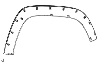
2. REMOVE NO. 1 FRONT WHEEL OPENING EXTENSION PAD
(a) Using a heat light, heat the front fender wheel opening moulding.
|
(b) Remove the No. 1 front wheel opening extension pad. |
|
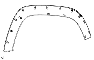
3. REMOVE FRONT WHEEL OPENING EXTENSION PAD
(a) Using a heat light, heat the front fender wheel opening moulding.
|
(b) Remove the front wheel opening extension pad. |
|
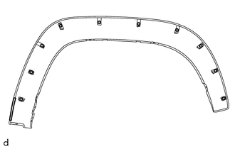
4. REMOVE NO. 3 BODY OUTSIDE MOULDING PAD
(a) Using a heat light, heat the quarter panel wheel opening moulding.
|
(b) Remove the No. 3 body outside moulding pad. |
|
5. REMOVE NO. 2 BODY OUTSIDE MOULDING PAD
(a) Using a heat light, heat the quarter panel wheel opening moulding.
|
(b) Remove the No. 2 body outside moulding pad. |
|
6. REMOVE NO. 1 BODY OUTSIDE MOULDING PAD
(a) Using a heat light, heat the quarter panel wheel opening moulding.
|
(b) Remove the No. 1 body outside moulding pad. |
|
 Components
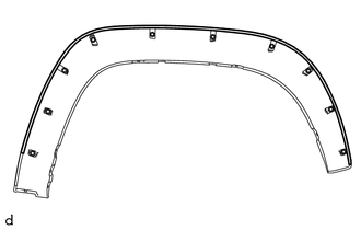
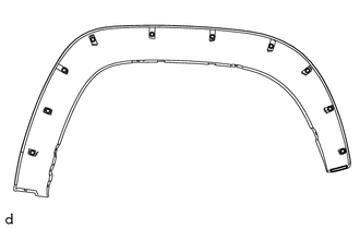
COMPONENTS
ILLUSTRATION
ILLUSTRATION
...
 Reassembly
REASSEMBLY
CAUTION / NOTICE / HINT
HINT:
Use the same procedure for the RH side and LH side.
The following procedure is for the LH side.
When installing a new front wheel opening ex ...
Other materials:
ECU Power Source Circuit
WIRING DIAGRAM
CAUTION / NOTICE / HINT
NOTICE:
Inspect the fuses for circuits related to this system before performing the following
inspection procedure.
PROCEDURE
1.
INSPECT BATTERY
(a) Check the battery voltage.
Standard voltage:
11 to 14 V
NG
...
On-vehicle Inspection
ON-VEHICLE INSPECTION
PROCEDURE
1. INSPECT ENGINE COOLANT
(See page )
2. INSPECT ENGINE OIL
(See page )
3. INSPECT BATTERY
(See page )
4. INSPECT SPARK PLUG
(See page )
5. INSPECT AIR CLEANER FILTER ELEMENT SUB-ASSEMBLY
(a) Remove the air cleaner filter element sub-assembly.
(b) Visu ...
Removal
REMOVAL
PROCEDURE
1. REMOVE REAR SEAT CUSHION ASSEMBLY
(a) Remove the 6 bolts and 2 rear seat cushion assemblies.
2. REMOVE NO. 4 ROOM PARTITION COVER LH
3. REMOVE NO. 4 ROOM PARTITION COVER RH
4. REMOVE NO. 3 ROOM PARTITION COVER
...
