Toyota Tacoma (2015-2018) Service Manual: Disassembly
DISASSEMBLY
PROCEDURE
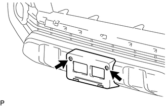
1. REMOVE FRONT LICENSE PLATE BRACKET
|
(a) Remove the 2 screws and front license plate bracket. |
|
2. REMOVE NO. 4 ENGINE ROOM WIRE (w/ Fog Light)
|
(a) Disconnect the 2 connectors. |
|
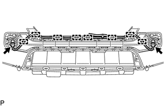
(b) Disengage the 8 clamps to remove the No. 4 engine room wire.
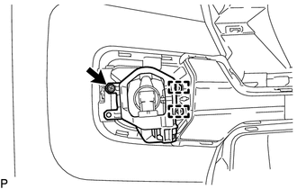
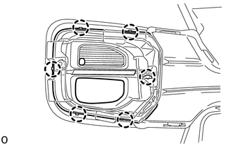
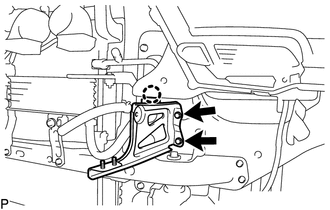
3. REMOVE FOG LIGHT ASSEMBLY LH (w/ Fog Light)
|
(a) for Halogen Fog Light: (1) Remove the screw. (2) Disengage the 2 guides to remove the fog light assembly LH. |
|
|
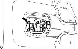
(b) for LED Fog Light: (1) Remove the screw. (2) Disengage the 2 guides to remove the fog light assembly LH. |
|
4. REMOVE FOG LIGHT ASSEMBLY RH (w/ Fog Light)
HINT:
Use the same procedure as for the LH side.
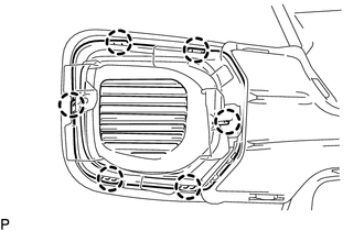
5. REMOVE FOG LIGHT COVER LH (w/ Fog Light)
|
(a) for Halogen Fog Light: (1) Disengage the 6 claws to remove the fog light cover LH. |
|
|
(b) for LED Fog Light: (1) Disengage the 6 claws to remove the fog light cover LH. |
|
6. REMOVE FOG LIGHT COVER RH (w/ Fog Light)
HINT:
Use the same procedure as for the LH side.
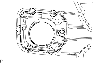
7. REMOVE FRONT BUMPER HOLE COVER LH (w/o Fog Light)
|
(a) Disengage the 6 claws to remove the front bumper hole cover LH. |
|
8. REMOVE FRONT BUMPER HOLE COVER RH (w/o Fog Light)
HINT:
Use the same procedure as for the LH side.
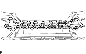
9. REMOVE LOWER NO. 1 RADIATOR GRILLE
|
(a) Disengage the 23 claws to remove the lower No. 1 radiator grille. |
|
10. REMOVE FRONT VALANCE PANEL
|
(a) Remove the 2 outside moulding retainers. |
|
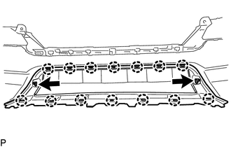
(b) Disengage the 14 claws to remove the front valance panel.
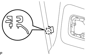
11. REMOVE FRONT FENDER LINER RETAINER
|
(a) Disengage the claw to remove the front fender liner retainer. |
|
12. REMOVE FRONT BUMPER UPPER CENTER RETAINER
|
(a) Disengage the 2 clamps to separate the wire harness. |
|
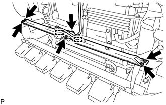
(b) Remove the 6 nuts and front bumper upper center retainer.
13. REMOVE RADIATOR SIDE DEFLECTOR LH
|
(a) Remove the clip. |
|
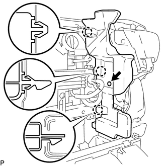
(b) Disengage the 3 claws to remove the radiator side deflector LH.
14. REMOVE RADIATOR SIDE DEFLECTOR RH
HINT:
Use the same procedure as for the LH side.
15. REMOVE FRONT BUMPER ARM MOUNTING BRACKET LH
|
(a) Remove the 2 bolts. |
|
(b) Disengage the claw to remove the front bumper arm moulding bracket LH.
16. REMOVE FRONT BUMPER ARM MOUNTING BRACKET RH
HINT:
Use the same procedure as for the LH side.
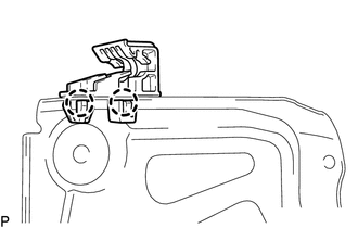
17. REMOVE HEADLIGHT MOUNTING BRACKET
|
(a) Disengage the 2 claws to remove the headlight mounting bracket. HINT: Use the same procedure for the RH side and LH side. |
|
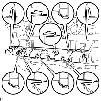
18. REMOVE FRONT BUMPER ENERGY ABSORBER
|
(a) Disengage the 9 claws and guide to remove the front bumper energy absorber. |
|
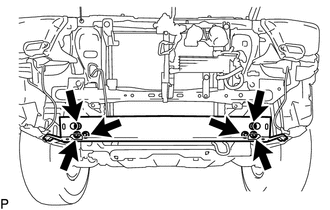
19. REMOVE FRONT BUMPER REINFORCEMENT
|
(a) Remove the 6 nuts and front bumper reinforcement. |
|
20. REMOVE FRONT BUMPER INNER ARM SUB-ASSEMBLY LH
(a) Put a 7 mm (0.276 in.) drill bit into a drill.
(b) Wind tape around the drill bit approximately 5 mm (0.197 in.) from the tip of the drill as shown in the illustration.
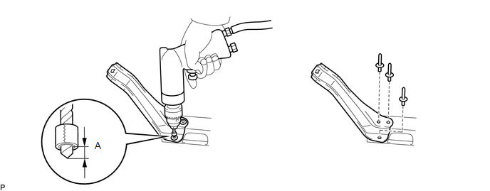
Standard:
|
Area |
Specified Condition |
|---|---|
|
A |
5 mm (0.197 in.) |
HINT:
Tape the 7 mm (0.276 in.) drill bit to prevent the drill bit from going too deep.
(c) Lightly press the drill against the 3 rivets and drill off the flanges of the 3 rivets.
CAUTION:
Be careful of the drilled rivet as it may become hot.
NOTICE:
- Pressing the drill too firmly will cause the rivet to turn and result in the rivet not being drilled through.
- Do not pry the rivet with the drill because this may cause damage to the installation holes of the rivet or the drill bit.
(d) Remove the front bumper inner arm sub-assembly LH.
(e) Using a vacuum cleaner, remove the rivet fragments and shavings from the drilled area.
21. REMOVE FRONT BUMPER INNER ARM SUB-ASSEMBLY RH
HINT:
Use the same procedure as for the LH side.
22. REMOVE LOWER FRONT BUMPER RETAINER
HINT:
Use the same procedure for both lower front bumper retainers.
(a) Put a 7 mm (0.276 in.) drill bit into a drill.
(b) Wind tape around the drill bit approximately 5 mm (0.197 in.) from the tip of the drill as shown in the illustration.
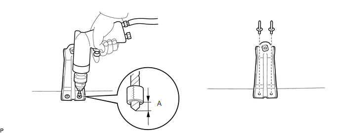
Standard:
|
Area |
Specified Condition |
|---|---|
|
A |
5 mm (0.197 in.) |
HINT:
Tape the 7 mm (0.276 in.) drill bit to prevent the drill bit from going too deep.
(c) Lightly press the drill against the 2 rivets and drill off the flanges of the 2 rivets.
CAUTION:
Be careful of the drilled rivet as it may become hot.
NOTICE:
- Pressing the drill too firmly will cause the rivet to turn and result in the rivet not being drilled through.
- Do not pry the rivet with the drill because this may cause damage to the installation holes of the rivet or the drill bit.
(d) Remove the lower front bumper retainer.
(e) Using a vacuum cleaner, remove the rivet fragments and shavings from the drilled area.
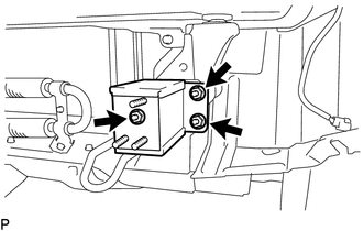
23. REMOVE NO. 2 FRONT BUMPER EXTENSION SUB-ASSEMBLY LH
|
(a) Remove the 3 nuts and No. 2 front bumper extension sub-assembly LH. |
|
24. REMOVE NO. 2 FRONT BUMPER EXTENSION SUB-ASSEMBLY RH
HINT:
Use the same procedure as for the LH side.
25. REMOVE FRONT BUMPER COVER INSERT LH
|
(a) Remove the bolt. |
|
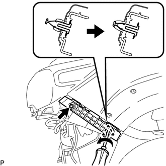
(b) Using a screwdriver, disengage the clip to remove the front bumper cover insert LH as shown in the illustration.
26. REMOVE FRONT BUMPER COVER INSERT RH
HINT:
Use the same procedure as for the LH side.
 Components
COMPONENTS
ILLUSTRATION
*A
w/ Front Spoiler
-
-
*1
RADIATOR GRILLE
*2
FRONT NO. 1 WHEEL OPENING EXTENS ...
 Reassembly
REASSEMBLY
PROCEDURE
1. INSTALL FRONT BUMPER COVER INSERT LH
(a) Engage the clip to install the front bumper cover insert LH.
(b) Install the b ...
Other materials:
4wd Control Ecu
Components
COMPONENTS
ILLUSTRATION
Installation
INSTALLATION
PROCEDURE
1. INSTALL 4 WHEEL DRIVE CONTROL ECU
(a) Engage the 2 guides to install the 4 wheel drive control ECU.
(b) Install the 2 bolts.
Torque:
5.0 N·m {51 kgf·cm, 44 in·lbf}
(c) Connect the 2 connectors.
2. INSTALL ...
Check Bus 3 Line for Short to +B
DESCRIPTION
There may be a short circuit between one of the CAN bus lines and +B when no
resistance exists between terminal 6 (CA3H) of the central gateway ECU (network
gateway ECU) and terminal 16 (BAT) of the DLC3, or terminal 21 (CA3L) of the central
gateway ECU (network gateway ECU) and t ...
Cruise Control System Internal Failure (P057504,P057549)
DESCRIPTION
This is output when the ECM detects malfunctions in the internal circuit.
DTC Code
DTC Detection Condition
Trouble Area
MIL
Note
P057504
Vehicle Condition:
Cruise control in operation
...
