Toyota Tacoma (2015-2018) Service Manual: Disassembly
DISASSEMBLY
PROCEDURE
1. INSPECT FRONT DRIVE SHAFT
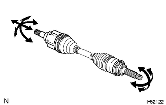
(a) Check whether there is no remarkable play in the outboard joint.
(b) Check whether the inboard joint slides smoothly in the thrust direction.
(c) Check whether there is no remarkable play in the radial direction of the inboard joint.
(d) Check the boots for damage.
NOTICE:
Move the drive shaft while keeping it level.
2. REMOVE FRONT AXLE INBOARD JOINT BOOT CLAMP
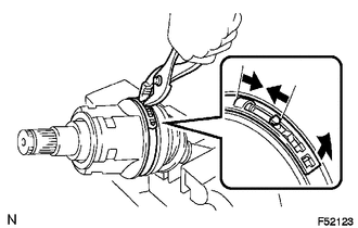
(a) Using pliers, disengage the hooks together and remove the large clamp.
(b) Using a side cutter, cut the small boot clamp.
3. SEPARATE INBOARD JOINT BOOT
(a) Slide the inboard joint boot toward the outboard joint.
4. REMOVE FRONT DRIVE INBOARD JOINT ASSEMBLY
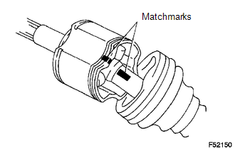
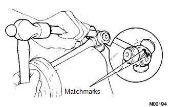
(a) Place matchmarks on the inboard joint and outboard joint shaft.
NOTICE:
Do not punch the marks.
(b) Remove the inboard joint from the outboard joint shaft.
|
(c) Using a snap ring expander, remove the snap ring. |
|
|
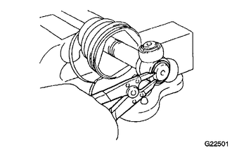
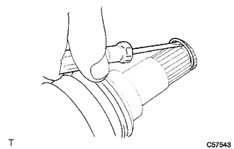
(d) Place matchmarks on the outboard joint shaft and tripod. NOTICE: Do not punch the marks. |
|
(e) Using a brass bar and hammer, remove the tripod from the outboard joint shaft.
NOTICE:
Do not tap the roller.
(f) Remove the inboard joint boot from the outboard joint shaft.
5. REMOVE FRONT AXLE OUTBOARD JOINT BOOT CLAMP
(a) Using a side cutter, cut the boot clamps.
6. REMOVE OUTBOARD JOINT BOOT
(a) Remove the outboard joint boot from the outboard joint shaft.
7. REMOVE FRONT DRIVE INNER SHAFT OUTER SHAFT SNAP RING
(a) Using a screwdriver, remove the snap ring.
8. REMOVE FRONT DRIVE SHAFT DUST COVER
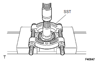
(a) Using SST and a press, remove the dust cover.
SST: 09950-00020
9. REMOVE FRONT AXLE HUB OIL SEAL
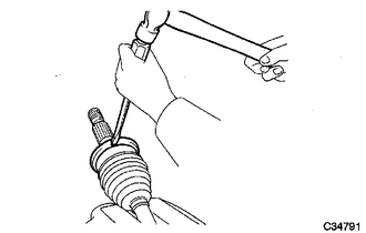
(a) Using a screwdriver and a hammer, remove the oil seal.
 Components
COMPONENTS
ILLUSTRATION
ILLUSTRATION
...
 Removal
REMOVAL
PROCEDURE
1. REMOVE FRONT WHEEL
2. DRAIN DIFFERENTIAL OIL
3. SEPARATE FRONT SPEED SENSOR
(a) Remove the bolt and separate the front speed sensor.
(b) Disengage the 2 clamps.
(c) Remov ...
Other materials:
Cruise SET Indicator Light Circuit
DESCRIPTION
The ECM illuminates the cruise control SET indicator by sending indicator output
demand signals to the combination meter assembly via CAN communication. The cruise
control SET indicator illuminates when the dynamic radar cruise control system is
controlling vehicle speed. The crui ...
Removal
REMOVAL
PROCEDURE
1. REMOVE PROPELLER SHAFT WITH CENTER BEARING ASSEMBLY
(a) Place matchmarks on the propeller shaft flange and differential flange.
Text in Illustration
*a
Matchmark
...
Test Mode Procedure
TEST MODE PROCEDURE
1. WARNING LIGHT AND INDICATOR LIGHT INITIAL CHECK
(a) When the ignition switch is turned ON, check that the ABS warning, brake
warning, and slip indicator lights come on for approximately 3 seconds.
HINT:
When the brake fluid level is low, the brake warning light c ...
