Toyota Tacoma (2015-2018) Service Manual: Components
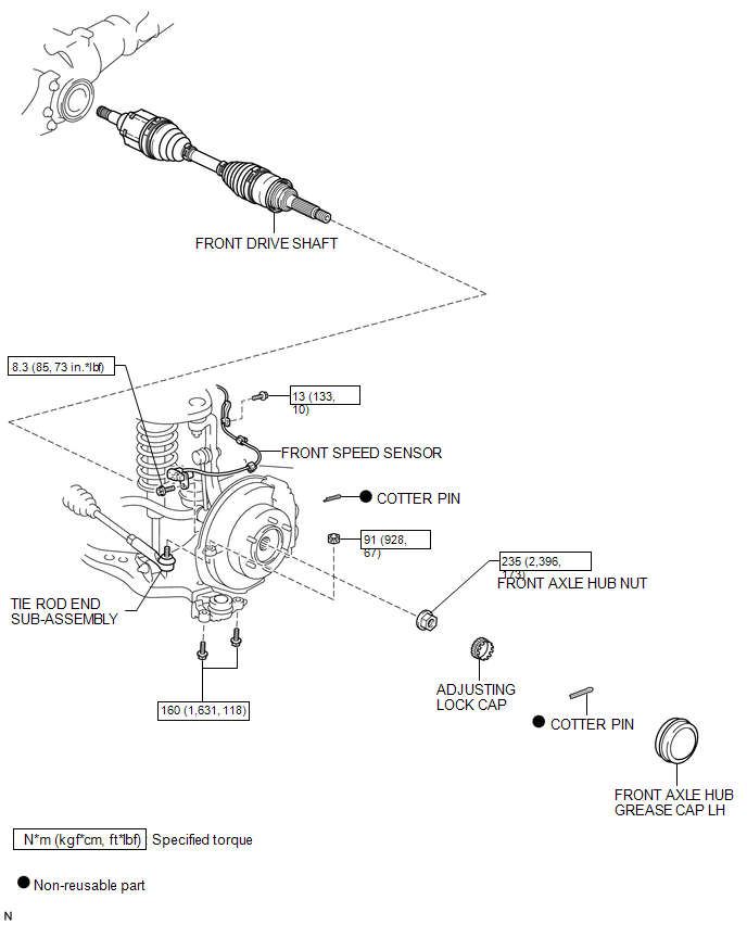
COMPONENTS
ILLUSTRATION
ILLUSTRATION
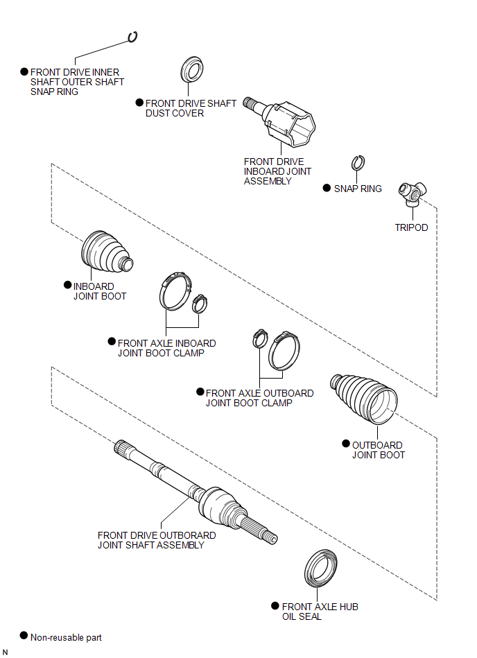

 Disassembly
DISASSEMBLY
PROCEDURE
1. INSPECT FRONT DRIVE SHAFT
(a) Check whether there is no remarkable play in the outboard joint.
(b) Check whether the inboard joint slides smoothly in the thrust directio ...
Other materials:
Dtc Check / Clear
DTC CHECK / CLEAR
1. CHECK DTC
(a) Connect the Techstream to the DLC3.
(b) Turn the ignition switch to ON.
(c) Turn the Techstream on.
(d) Enter the following menus: Body Electrical / (desired system) / Trouble Codes.
(e) Check the details of the DTC(s) (See page
).
2. CLEAR DTC
(a) Connec ...
Removal
REMOVAL
PROCEDURE
1. DISCONNECT TRANSMISSION WIRE
(See page )
2. REMOVE VALVE BODY OIL STRAINER ASSEMBLY
(a) Remove the 3 bolts and valve body oil strainer assembly from the
transmission valve body assembly.
3. REMOVE TRANSMISSION VALVE ...
Voice Guidance does not Function
PROCEDURE
1.
CHECK VOICE GUIDANCE SETTING
(a) Check that the voice guidance setting is not off.
OK:
Voice guidance setting is not off.
NG
CHANGE THE VOICE GUIDANCE SETTING TO ON
OK
...
