Toyota Tacoma (2005–2015) Owners Manual: Detachable pole antenna
The antenna can be removed.
■ Removing the antenna
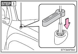
Place the included wrench around the antenna.
When not in use, the wrench is stored in glove box.
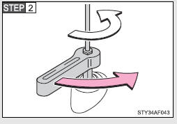
Loosen the antenna with the wrench and remove it.
■ Installing the antenna
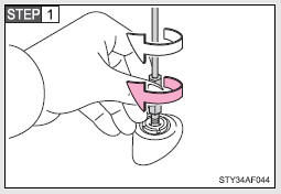
Tighten the antenna by one hand until it will not turn any more.
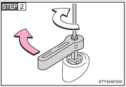
Using the wrench, tighten the antenna an additional 1/8th turn (20 to 45 degrees) to secure it in place.
After tightening the antenna, remove the wrench.
■About the wrench
●A standard 5/16 in. (8 mm) wrench can also be used to install or remove the antenna.
●After using the included wrench, store it in the glove box for safekeeping.
NOTICE
■To avoid damaging the antenna
Remove the antenna in the following situations.
●When using an automatic carwash.
●When the antenna will touch the ceiling of a garage, etc.
●When covering the vehicle with a car cover.
■Removing the antenna
●For normal driving, make sure the antenna is installed.
●When removing the antenna to use an automatic carwash, etc., be careful not to lose the antenna. Also, make sure to reinstall the antenna before driving the vehicle.
■Using the wrench
●When installing or removing the antenna, use the included wrench or a standard 5/16 in. (8 mm) wrench.
●Be careful not to scratch or damage the vehicle body with the wrench.
●Do not over-tighten the antenna.
Over-tightening may damage the antenna.
●Do not use pliers to install or remove the antenna.
Pliers may damage the antenna’s finish.
 Operating the sub woofer (on some Access Cab models)
OFF
ON
LIGHT ON
The sub woofer illumination turns on. In this position, the sub woofer operates. ...

Other materials:
Compressor Lock Sensor Circuit (B1422)
SYSTEM DESCRIPTION
The ECM sends the engine speed signal to the air conditioning amplifier assembly
via CAN communication.
The air conditioning amplifier assembly reads the difference between compressor
speed and engine speed. When the difference becomes too large, the air conditioning
ampli ...
Replacement
REPLACEMENT
CAUTION / NOTICE / HINT
NOTICE:
Immediately wash off any brake fluid that comes into contact with any painted
surfaces.
HINT:
If any work is done on the brake system or if air in the brake lines is suspected,
bleed the air from the system.
PROCEDURE
1. FILL RESERVOIR WITH BRAK ...
Fuel Sender Gauge Assembly
Components
COMPONENTS
ILLUSTRATION
Inspection
INSPECTION
PROCEDURE
1. INSPECT FUEL SENDER GAUGE ASSEMBLY
(a) Check that the float moves smoothly between F and E.
Text in Illustration
*a
Component without harness connected
(Fuel Sen ...
