Toyota Tacoma (2015-2018) Service Manual: Microphone Circuit between Microphone and Radio Receiver
DESCRIPTION
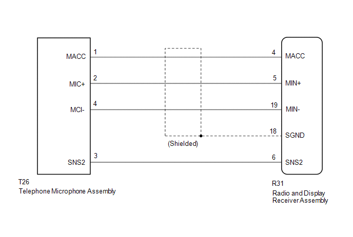
The radio and display receiver assembly and telephone microphone assembly are connected to each other using the microphone connection detection signal lines.
Using this circuit, the radio and display receiver assembly sends power to the telephone microphone assembly, and the telephone microphone assembly sends microphone signals to the radio and display receiver assembly.
WIRING DIAGRAM
PROCEDURE
|
1. |
CHECK MICROPHONE |
|
(a) Enter the "Microphone Check" screen. Refer to Check Microphone in Operation Check. Click here |
|
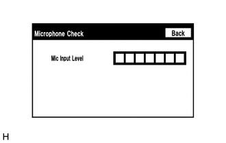
(b) When a voice is input into the microphone, check that the microphone input level meter changes according to the input voice.
OK:
Check result is normal.
| OK | .gif) |
PROCEED TO NEXT SUSPECTED AREA SHOWN IN PROBLEM SYMPTOMS TABLE |
|
.gif)
|
2. |
CHECK HARNESS AND CONNECTOR (RADIO AND DISPLAY RECEIVER ASSEMBLY - TELEPHONE MICROPHONE ASSEMBLY |
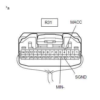
(a) Disconnect the R31 radio and display receiver assembly connector.
(b) Disconnect the T26 telephone microphone assembly connector.
(c) Measure the resistance according to the value(s) in the table below.
Standard Resistance:
|
Tester Connection |
Condition |
Specified Condition |
|---|---|---|
|
R31-4 (MACC) - T26-1 (MACC) |
Always |
Below 1 Ω |
|
R31-5 (MIN+) - T26-2 (MIC+) |
Always |
Below 1 Ω |
|
R31-19 (MIN-) - T26-4 (MIC-) |
Always |
Below 1 Ω |
|
R31-6 (SNS2) - T26-3 (SNS2) |
Always |
Below 1 Ω |
|
R31-4 (MACC) - Body ground |
Always |
10 kΩ or higher |
|
R31-5 (MIN+) - Body ground |
Always |
10 kΩ or higher |
|
R31-19 (MIN-) - Body ground |
Always |
10 kΩ or higher |
|
R31-18 (SGND) - Body ground |
Always |
10 kΩ or higher |
|
R31-6 (SNS2) - Body ground |
Always |
10 kΩ or higher |
(d) Reconnect the radio and display receiver assembly connector.
(e) Reconnect the telephone microphone assembly connector.
| NG | |
REPAIR OR REPLACE HARNESS OR CONNECTOR |
|
|
3. |
INSPECT RADIO AND DISPLAY RECEIVER ASSEMBLY |
(a) Remove the radio and display receiver assembly with connectors still connected.
|
(b) Measure the voltage according to the value(s) in the table below. Standard Voltage:
|
|
(c) Measure the resistance according to the value(s) in the table below.
Standard Resistance:
|
Tester Connection |
Condition |
Specified Condition |
|---|---|---|
|
R31-19 (MIN-) - Body ground |
Always |
Below 1 Ω |
|
R31-18 (SGND) - Body ground |
Always |
Below 1 Ω |
| NG | |
REPLACE RADIO AND DISPLAY RECEIVER ASSEMBLY |
|
|
4. |
INSPECT TELEPHONE MICROPHONE ASSEMBLY |
|
(a) Remove the telephone microphone assembly. Click here |
|
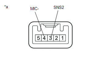
(b) Measure the resistance according to the value(s) in the table below.
Standard Resistance:
|
Tester Connection |
Condition |
Specified Condition |
|---|---|---|
|
3 (SNS2) - 4 (MIC-) |
Always |
Below 1 Ω |
(c) Install the telephone microphone assembly.
Click here .gif)
| NG | |
REPLACE TELEPHONE MICROPHONE ASSEMBLY |
|
|
5. |
INSPECT TELEPHONE MICROPHONE ASSEMBLY |
|
(a) Turn the ignition switch to ACC. |
|
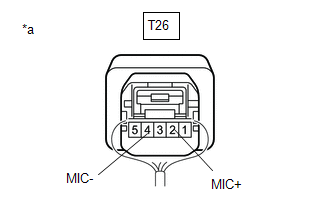
(b) Connect an oscilloscope to terminals 2 (MIC+) and 4 (MIC-) of the telephone microphone assembly connector.
(c) Check the waveform of the telephone microphone assembly using the oscilloscope.
Result|
Result |
Proceed to |
|---|---|
|
A waveform synchronized with the voice input to the amplifier microphone assembly is output |
A |
|
A waveform synchronized with the voice input to the amplifier microphone assembly is not output |
B |
| A | |
PROCEED TO NEXT SUSPECTED AREA SHOWN IN PROBLEM SYMPTOMS TABLE |
| B | |
REPLACE TELEPHONE MICROPHONE ASSEMBLY |
 Data Signal Circuit between Radio Receiver and Extension Module
DESCRIPTION
The stereo component tuner assembly sends the image data signal to the radio
and display receiver assembly via this circuit.
WIRING DIAGRAM
PROCEDURE
1.
CHEC ...
 Radio Receiver Power Source Circuit
DESCRIPTION
This is the power source circuit to operate the radio and display receiver assembly.
WIRING DIAGRAM
CAUTION / NOTICE / HINT
NOTICE:
Inspect the fuses for circuits related to ...
Other materials:
Disassembly
DISASSEMBLY
PROCEDURE
1. REMOVE OIL PUMP RELIEF VALVE
(a) Using a 27 mm socket wrench, remove the oil pump relief valve plug.
(b) Remove the oil pump relief valve spring and oil pump relief valve.
(c) Remove the spring and relief valve.
2. R ...
Tire Pressure Monitor ECU Communication Stop Mode
DESCRIPTION
Detection Item
Symptom
Trouble Area
Tire Pressure Monitor ECU Communication Stop Mode
Either condition is met:
Communication stop for "Tire Pressure2" is indicated on the
"Communication Bus C ...
AUTO LSD Indicator Light Remains ON
DESCRIPTION
During normal mode, pressing the VSC OFF switch for a short amount of time changes
vehicle to AUTO LSD mode.
WIRING DIAGRAM
CAUTION / NOTICE / HINT
NOTICE:
When replacing the brake actuator assembly, perform calibration (See page
).
PROCEDURE
1.
CHECK ...
