Toyota Tacoma (2015-2018) Service Manual: Components
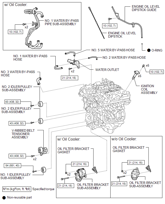
COMPONENTS
ILLUSTRATION
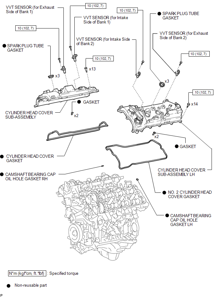
ILLUSTRATION
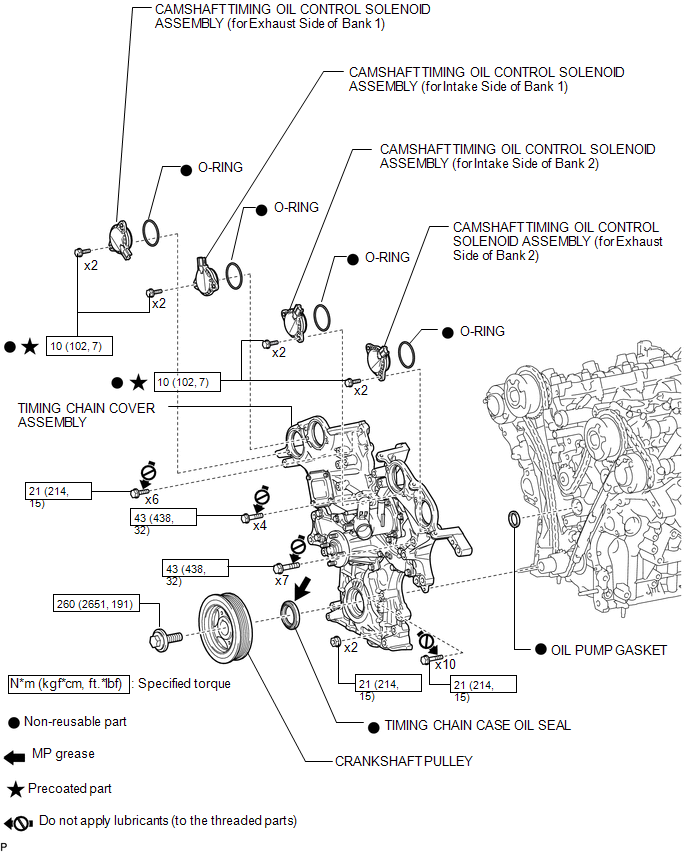
ILLUSTRATION
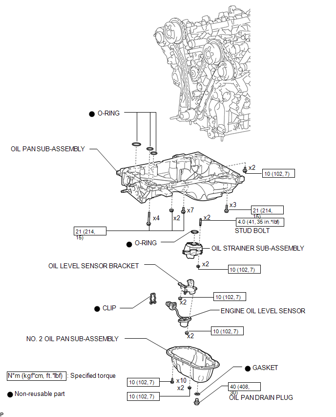
ILLUSTRATION
ILLUSTRATION
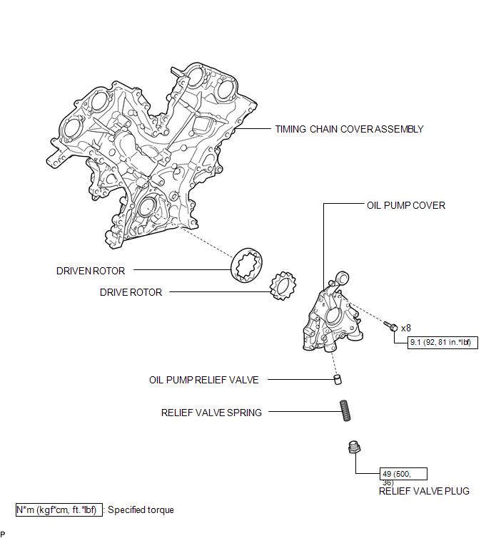
 Oil Pump
...
 Disassembly
DISASSEMBLY
PROCEDURE
1. REMOVE OIL PUMP RELIEF VALVE
(a) Using a 27 mm socket wrench, remove the oil pump relief valve plug.
(b) Remove the oil pump relief valve spring and oil pump re ...
Other materials:
Parts Location
PARTS LOCATION
ILLUSTRATION
ILLUSTRATION
ILLUSTRATION
ILLUSTRATION
...
Tachometer Malfunction
DESCRIPTION
In this circuit, the meter CPU receives engine speed signals from the ECM using
the CAN communication system (CAN V1 Bus). The meter CPU displays the engine speed
calculated based on the data received from the ECM.
WIRING DIAGRAM
PROCEDURE
1.
CHECK CAN CO ...
Dtc Check / Clear
DTC CHECK / CLEAR
1. START DIAGNOSTIC MODE
HINT:
Illustrations may differ from the actual vehicle screen depending on
the device settings and options. Therefore, some detailed areas may not
be shown exactly the same as on the actual vehicle screen.
If the system cannot enter d ...
